The 3TL Count Down
# 10 Tool Box
This is one cool tool box and present from Erica ... and made to a very high standard too. They will go well in the workshop I plan to build when I get to the US. The attention to detail is superb, although I wish they'd made the pliers move, I feel a modification coming on!


# 9 Tamiya 1/6 Scale Monkey Bike
I've been after one of these for years. This one came up on eBay UK and was a real bargain, another eBay gem and cheap at half the price. It's the 2000 Anniversary Edition with several extra parts for a customized version. The extra parts will make nice props laying around the 1/6 scale workshop.

# 8 Minichamps Honda CB 750 Four
This was an excellent find from Nortons Trade Only Toy Store in Leicestershire UK that I sometimes go to, I knew having my own business would come in useful some day. The boxed Honda was thrown, and I mean thrown, in a bargain bin. There were about 4 in there and 'super' marked down. I spent some time trying to find the best out of a bad lot and settled on this one. I took it apart so as to repair the bits that had either fallen off or were broken off. I will rebuild it in 2012.


# 7 Folding Chairs
These were a Christmas present from Erica and they are ACE! I have a set of 4 and they are so cool. They'll look great in my planned room sets on hold at present until I get to the US.


# 6 Vespa Scooter 150 VL 1T (1955) by New Ray
Another eBay find but it was badly damaged, smashed to bits to be exact. A total rebuild was undertaken and a change of colour made too, from the standard white to pale blue. I dismantled every component and repaired all the broken parts, just about everything was damaged. I re-bushed the wheels and held them in place with tiny nylock nuts, they also look more scale like. The seat hand rail was missing and so was the main stand, both were fabricated from K & S stock brass wire and strip. The finished repair was then painted using automotive paint and detail added using a brush


# 5 Tamiya Vintage Honda CB 750 Four Kit
The last time I had this kit I was 12 and have wanted to get another for many years. I didn't want the new version as some of the contents differ from the original 70's kit. The first item to go was the individual metal link chain now it's just a solid plastic offering. This was yet another eBay win and sooooo cheap. It was listed in the wrong category and had been part build and bits were missing, allegedly, but on receipt all the parts were found to be present. It had, however, been painted gold!! It took a very long time to remove the gold paint even with the use of an industrial ultrasonic cleaner. It's now waiting to get built.


# 4 Boots
Another great gift from Erica. These superb boots are just like real ones but tiny! How do they sew them together? we'll probable never know! My guess is they must be using some form of miniaturization machine, I want one!!


# 3 Kayak
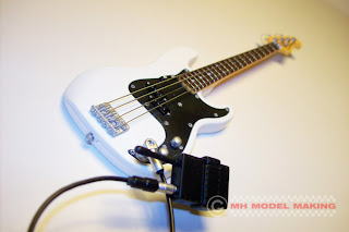
#2 Guitar
Well, that's all folks, I'll keep my eyes open for more toys during 2012...
Wow, cool or what! Erica found this one too. I was trying to guess what this present was for ages and failed miserably. I came up with all sorts of ideas and none as it turned out were even close. It works a treat and was duly test in a bath if cold water and passed admirably.


#2 Guitar
Double wow with bells on, thanks to Erica again... Just something else made using that miniaturization machine, indistinguishable from the real thing, apart from the size that is.

# 1 Tirrem Mesu
Erica created Tirrem for me after I had asked if I could have a Merritt making. 'No, there will only be ONE Merrit' came the reply. So I came up with Tirrem, Merrit spelt in reverse, pretty good hey!! and the surname just had to be Mesu : ) I must say he's turned out very well thanks to Erica's creativity. She worked like a demon getting him all finished for Christmas but she came up trumps again.


Well, that's all folks, I'll keep my eyes open for more toys during 2012...