Sunday 26 June 2011

Nieuport Build Part 11 - Fitting Control Horns and Aileron Bell-cranks

Now that all the control horns and bell-cranks have been made from paxolin they can now be 'dry fit' into each appropriate slot.

The revised elevator horns are located in the same position as that shown on the plan. All that needs to be done it to saw a slot into the leading edge of each elevator.

This slot has to be deep enough to allow the semicircular cut-out in the horn to sit behind the carbon fibre tube when fitted.


Slot cut into elevator leading edge.


Paxolin horn 'dry fit' into elevator.
These horns will be permanently glued in place after covering.


The tube and horn both 'dry fit' into elevator.


The carbon fibre tube should fit tight up against the back of the rebate. If the tube rocks on the horn it's just a simple task of making the slot for the horn a little deeper, until  the tube stops rocking.


Stabilizer and elevator temporarily assembled.


Close-up of starboard elevator.


Close-up of elevator control horn and hinge detail.
   
The above picture also shows a mounting hole in the gusset for the stabilizer bracing tube to bolt to. A tube is inserted into this hole to act as a 'compression tube' to prevent the wood being crushed when you tighten up the nut and bolt.


Next came the rudder horn. This was fitted in place in the same manner as that use for the elevator horns. Again making sure that the carbon fibre tube fits into the rebate correctly.


The slot for the horn is cut out ready
for the horn and tube to be 'dry fit'


 Horn in place, 'dry fit', and the hinge strap cut-out.


Horn and tube in place, 'dry fit'.


And finally I 'dry fit' the aileron bell-cranks. Each torque tube was pushed through the wing ribs and into the bell-crank box. The bell-crank was then pushed onto the end of the tube and the tube and bell-crank pushed into the plywood wing rib (this plywood rib acts as the bearing for the tube) and the 'scale' rear spar was also pushed into place.


  Torque tube being pushed into position.
Also seen, the bell-crank and 'scale' rear spar.


Bell-crank components in place, 'dry-fit'.


Plan view of Bell-crank components, 'dry-fit'.


To prevent the aileron bell-crank from rotating on the torque tube it will be necessary to key the two items together with a metal dowel. Slots will be cut in the hole of the aileron bell-crank that the torque tube passes through. A hole is then drilled through the torque tube and a short metal dowel is inserted into this hole. On final assembly the torque tube and pin will be glued into the bell-crank hole and once the glue has cured the bell-crank will be unable to rotate around the tube.


Sketch showing metal dowel detail.


In the next post I'll be fitting the rigging brackets to the top and lower wing panels.


To be continued...

Saturday 18 June 2011

Cutting with a Fretsaw

Workshop Tip No. 6
When fretsawing, if the items you are cutting out have small fiddly holes or shapes cut into them make sure you cut these apertures out first.

It is far easier and safer to cut these apertures out when the item is still attached to the sheet. Your task will be made that much harder trying to drill and cut out the apertures after the main item has been removed from the sheet.

 The apertures in these bell-cranks were all cut out before 
the main component was cut from the sheet material.

You should also use a fretsaw cutting table when cutting out components. This will help support either side of the cut and help prevent the  component or blade from breaking.


 Simple fretsaw cutting table made from MDF, a clamp and fretsaw.

Nieuport Build Part 10 - Making Control Horns, Bell-cranks and Rigging Brackets

I wanted to change the paxolin control horns supplied with the kit so that the shape was closer to those used on the full size plane. The aileron horns were discarded as torque tubes are now being used. That left 2 elevator horns, 1 rudder horn and the 2 torque tube aileron bell-cranks.

First I traced the elevator and rudder horns from an engineering drawing I have of the full size plane. Worked out the percentage of enlargement for each item and then printed them out on to paper via a desk top printer.

The enlargements were, as you can imagine quite rough, the original trace was at 1:48 scale and the printout was now at almost 1:3 scale. So the control horns were redrawn freehand on to tracing paper from the enlargements.

I folded a piece of tracing paper in half and drew half of the horn onto the tracing paper, using the enlargement as a guide. The fold line of the tracing paper being on the centre line of the horn. Whilst the trace was still folded in half I turned it over and transferred the horn outline onto the reverse side of the tracing paper using a pencil. When the trace was opened up it revealed the complete control horn outline. I also marked on each horn tracing the position for the carbon fibre tube.


Horn traces and HIPS marked up prior to trimming out.

You can also see from the above picture that I have transferred the traced image to a piece of white HIPS (
High Impact Polystyrene Sheet), also known as plastic card. The beauty of this material is that you only have to score the surface with a sharp knife then crack it to separate the wanted part from the waste.

After the plastic card templates had been cut out, cleaned up and pilot holes drilled I used the templates to scribe the shape onto the paxolin sheet. The paxolin sheet was first sanded down then the component shapes scribed on to the surface using a sharp implement.


  Elevator and rudder template horns cut out and pilot holes drilled.


Horns scribed onto the paxolin sheet ready fro cutting out.

After the shapes had been scribed onto the paxolin sheet, the sheet was given a wipe over with a tissue. The dust left on the surface from sanding fills in the scribed lines and makes them more visible and easier to follow when cutting them out with a fretsaw. 


Here you can see the 3 finished horns cut out and
cleaned up and with pilot holes drilled.


You can see in this picture the difference between the
revised horns and the horns supplied with the kit.


Next came the aileron bell-cranks, these I drew to suit my aileron torque tube system. They will look similar to the full size plane.

Rough sketch showing aileron torque tube bell-crank and spar detail.

The above picture shows a sketch of the aileron bell-crank and how it fits around the scale rear spar detail. The cut out in the bell-crank shown in the sketch is to allow the bell-crank to rotate around the scale spar.

After taking measurements from the wing centre section, position of scale spar and the 'travel' of the horn a trace was produced.
 
An aileron bell-crank trace was drawn up and from it a template cut from plastic card. The bell-crank outline was then scribed onto the surface of the paxolin sheet using the plastic card template as a guide. After the bell-crank shapes were scribed onto the surface of the paxolin they were wiped over with a tissue to fill the scribed lines with dust making the line more visible The apertures were then cut and pilot holes drilled and finally the bell-cranks were cut out using a fretsaw.

  
Bell-crank trace and bell-crank drawn onto
plastic card prior to trimming out.


Bell-crank template trimmed out and pilot hole drilled.


 Bell-crank scribed onto paxolin sheet ready for
cutting out with a fretsaw.


When fretsawing, if the items you are cutting out have small fiddly holes or shapes cut into them (like these bell-cranks) make sure you cut these apertures out first.

It is far easier and safer to cut these apertures out when the item is still attached to the sheet. Your task will be made that much harder trying to drill and cut out the apertures after the main item has been removed from the sheet.


Bell-cranks cut out,  pilot holes drilled and cleaned up.

The  aileron horns were cut from paxolin sheet, all apertures were cut out first.

Having made the paxolin horns and bell-cranks  I moved on to the rigging plates. These plates were made from stock mild steel strip as supplied in the kit. All the holes require marking out and drilling then filing to shape.

It's a good idea to mark up and drill pilot holes in just one bracket. This bracket can then used as a drilling template for all the others, saving time and keeping the holes consistent without measuring each bracket individually. After you have drilled the pilot holes these can then be opened up to the correct size and the brackets cleaned up and corners rounded off.


Finished rigging brackets and fixings.

It became apparent that I had used ALL the fixings for a bygone project!! So had to source replacements, this I duly did, from stock.


The next blog will show the control horns being fitted into the rudder and elevators and the bell-cranks being fitted onto the aileron torque tubes.


Workshop Tip No. 6
When fretsawing, if the items you are cutting out have small fiddly holes or shapes cut into them make sure you cut these apertures out first.

It is far easier and safer to cut these apertures out when the item is still attached to the sheet. Your task will be made that much harder trying to drill and cut out the apertures after the main item has been removed from the sheet.

 The apertures in these bell-cranks were all cut out before 
the main component was cut from the sheet material.


You should also use a fretsaw cutting table when cutting out components. This will help support either side of the cut and help prevent the  component or blade from breaking.


 Simple fretsaw cutting table made from MDF, a clamp and fretsaw.


To be continued... 

Thursday 16 June 2011

'Shadow' Sanding

Workshop Tip No. 5
When you are sanding down strip and block wood, leading edges or block wood wingtips (other items too) you can monitor the progress of the shape by holding the object to be checked up against a light source.

The light source should be from above and behind the item you are checking thus casting a shadow onto the shape being created. If you are sanding and shaping a trailing edge for instance when you hold it up to the light source a shadow will be cast along its length. If the shadow is true and symmetrical then you know your work is finished. It not, then keep sanding, a little at a time until a symmetrical shadow is created.

Nieuport Build Part 9 - Sanding and Shaping the Lower Wings

Do you know what the main problem is building biplanes and triplanes? Simple, you get to build more wings!! So I'm sorry if this post is comparable to the last but the lower wing needs sanding to shape too...I bet you're glad I'm not building a triplane!!


I first cut to length the spars, leading and trailing edges that ran past both root ribs and sanded everything flush.

Before trimming and sending.


 After, trimmed and sanded flush.

I then sanded the bottom of each wing panel using my plate glass sheet with abrasive paper fixed to it, sanding in a circular motion until flat, (I used this method on the top wing panels too but, forgot to mention it, sorry). After sanding the bottom of the 2 wing panels I applied masking tape to each of the 2 wing ribs inboard of the root ribs. The root ribs were then sanded to follow the exact shape of the inboard ribs.


Masking tape used to protect the other ribs whilst sanding root rib.


After the preliminary sanding was complete the lower wing panels were marked up in the same way as the top wing panels. All the lines were drawn on using a ball point pen, then the planing and sanding began.


Leading edge marked and being planed to shape.


Trailing edge marked and ready for shaping.


 The leading edge sanded to the correct profile.

A sanding block was used to sand the leading edge top and bottom until the correct profile was obtained. When sanding the top of the leading edge care should be taken so as not to catch the wing ribs and riblets with the sanding block. It is best to just pull the sanding block over the ribs keeping it parallel to the leading edge.


Keep sanding block parallel whilst pulling towards the leading edge.


Then finish off by sanding with fine abrasive paper wrapped around a wooden block. The block should always be kept at a slight angle and overhang the leading edge slightly so as not to catch and damage the ribs. If you sand parallel to the leading edge the front of the block will almost certainly hit the edge of a rib, causing it to split or break away from the structure.


Sanding block held at an angle and overhanging leading edge during sanding.
Sanding direction from left to right.


Using the sanding block like this will result in catching and breaking the ribs.
Sanding direction from left to right. 


When you sand down tailing and leading edges (other items too) you can check the progress of the shape by holding the object to be checked up against a light source. This light source should be from above and behind the item you are checking. For this reason the lights in my workshop are placed at 90 degrees to  the workbench. There is one strip light to the left and one to the right. The lights can be switched on individually, thus casting shadows from the left or from the right. I have tried to show this in the picture below. 


Back light used to cast a shadow on the sanded trailing edge.
The shadow is fairly straight, indicating that the sanding is consistent.


Finally the wingtips were sanded to shape. As you can see they are far easier to create then the top wing wingtips.


 Lower wingtip sanded to shape, top.


 Lower wingtip sanded to shape, underside.


 Finished lower wingtip, end view.


After the 2 lower wing panels had been sanded to shape they were put aside whilst I made the rigging brackets and control horns. Wow, I'm glad all that sanding is over!!


Workshop Tip No. 5
When you are sanding down strip and block wood, leading edges or block wood wingtips (other items too) you can monitor the progress of the shape by holding the object to be checked up against a light source.

The light source should be from above and behind the item you are checking thus casting a shadow onto the shape being created. If you are sanding and shaping a trailing edge for instance when you hold it up to the light source a shadow will be cast along its length. If the shadow is true and symmetrical then you know your work is finished. It not, then keep sanding, a little at a time until a symmetrical shadow is created.


To be continued...

Sunday 12 June 2011

Sanding Down 'High Spots'

Workshop Tip No. 4
When you need to sand down a 'high spot' it is sometimes possible to apply masking tape to either side of the 'high spot'. The masking tape will allow the sanding block to pass over the taped area but sand down the 'high spot'. If you sand through the tape before you have finished then remove the tape and apply a new piece.

This method can also be used if you are reinforcing the centre section of a polystyrene and wood veneer covered wing with either epoxy or polyester resin and glass cloth. Apply the masking tape to either side of the finished glassed area then sand it down. The tape will protect the surface, if you sand  through the tape remove it and apply a new piece. The last thing you want to do is sand down the thin wood veneer as it will greatly reduce the strength of the wing around that area of the centre section. The main reason for glassing the centre section in the first place is to reinforce this high stressed area, this will be greatly impaired if you sand down the wood veneer to either side.

Nieuport Build Part 8 - Sanding and Shaping the Top Wings

The first items I sanded down were the 2 aileron boxes. These would need sanding flush with the wing ribs top and bottom. The possible problem here is whilst you are happily sanding down the 'high spot', in this case the aileron boxes, you will inevitably sand down the wing ribs on either side, bad.

So it is a good idea to apply some masking tape to the top and bottom of each rib either side of the aileron boxes. The tape will prevent the sanding block from removing material from the ribs but will allow the material in the middle to be sanded down to the required amount. If you sand through the masking tape, at that point stop sanding and remove the old masking tape and reapply a fresh piece. When you are happy with the result remove the masking tape.


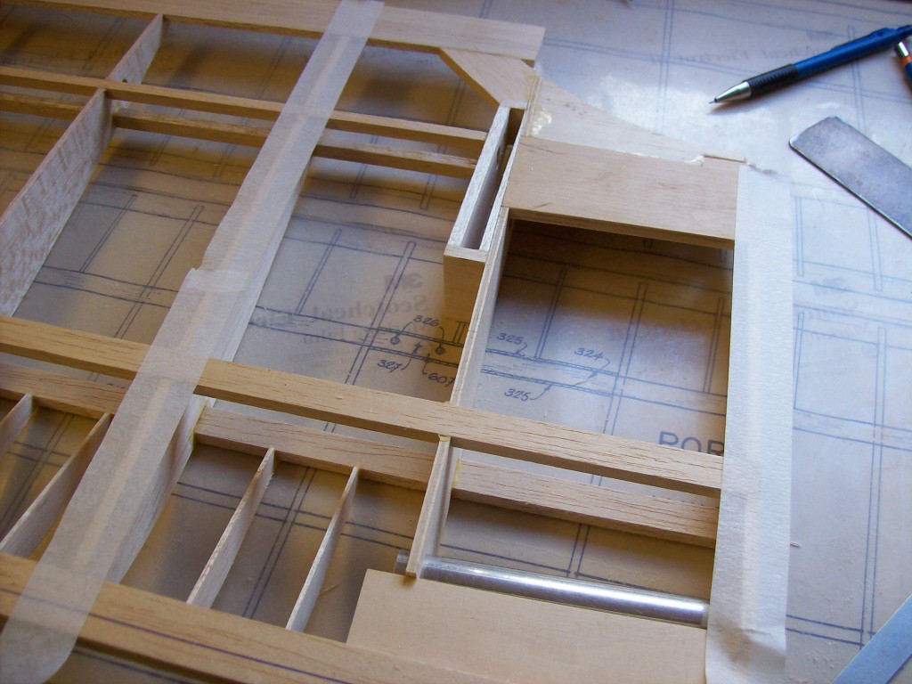
Here you see the masking tape in position prior to sanding.


 The sanding block being drawn over the aileron box. The ribs
 either side are protected with masking tape and will
remain untouched and their shape retained.


The same procedure was adopted for the top wing centre section.

The top wing components were then marked up ready for planing and sanding in the same way as the tailplane. A ball point pen was used for drawing the lines to the leading and trailing edges of the wings. The ailerons were also marked up, leading and trailing edges.


 Port wing leading edge marked up.


Trailing edge centre section marked up.


The angled line shown on the end grain of the centre section trailing edge in the above picture was derived at by extending a visual line from the top of the wing rib. When this is planed and sanded down it will follow the line of the wing rib. Because some of the wing ribs have a blunt end It may be necessary to extend the end of each rib that forms the aileron cut-out so a smooth section is achieved when covered. The other wing ribs that are glued to the tailing edge will not require extending and can be left as they are and will not show when covered.


Trailing edge marked up at aileron cut-out section.
When this is sanded down the rib should blend smoothly
into the trailing edge so as to achieve a good finish when covered.


 Aileron webbing cut-out marked up.


 Aileron leading edge marked up, rear.


Aileron leading edge marked up, front.
Also visible is the rebate for carbon fibre torque tube.

Next the surplus wood was fist planed off then sanded with a rough sanding block and then finished with a fine sanding block.


Wood being planed away from the wing aileron webbing and spar.
This was done slowly and carefully so as not to damage any of the wing ribs.


All the trailing edges were then planed down,
again taking care not to damage the wing ribs.


 A sanding block was then used to blend the ribs in with the trailing edge.
The trailing edge was rounded off later during the final stages.


 The top wing ribs were then sanded along with the front
edge of the leading edge to obtain the correct profile.


The lower section of the leading edge was
also planed and sanded to achieve the above profile.


 Problem area around the centre section.
During the sanding process I could see a problem area around the centre section. As can be seen from the above picture. The fabric would have struggled to blend nicely from the centre section block to the trailing edge. The answer was to add a further block of balsa and sand it to shape. This would act a 'land' for the fabric to fix to and to hold the shape along the curved cut-out of the centre section.


Additional balsa block glued in place.


 Balsa block after sanding, still requires a small amount of filler to finish.


 Using the finished panel as a template to mark up the next panel.


Each aileron tip section of the rebate needed filling in with balsa wood, the carbon fibre torque tube would then butt up against this block when finished. This infill is required so as to obtain the top and bottom aileron tip taper.


 Aileron tip before fitting balsa infill.


Aileron tip after fitting the balsa infill, this was sanded flush when dry.


 Planing down the the aileron leading edge.

The aileron leading edge was then planed down, taking care not to damage any wing ribs. The leading and trailing edges were then sanded down using masking tape to prevent sanding down the aileron ribs.

Tape applied to the ailerons to prevent sanding down the ribs.


Aileron tip tapers and trailing edge marked up ready to be sanded to shape.


 Sanding the wing tip taper, underside of starboard wing.

When I had finished sanding down both of the wingtip tapered supports top and bottom I moved on to the wingtips.

Wingtips are always a bit of an anomaly and the drawings can only show you so much. Wingtip sections are always welcome and the more you have on a drawing then all the better. So interpret the drawings as best you can, decide your plan of attack and stick to it. It helps if you can work the 2 together, this will help keep them looking the same during construction.

With this Nieuport kit the wingtips to the bottom wings are the easiest type to make as you can see from my earlier post but the top wing is a little trickier. So I hope you will find the following pictures showing my interpretation of the wingtips useful. But remember it's only my interpretation of what I deem right. Just try and achieve a nice flowing curve from leading edge to trailing edge and that will be fine.


The before picture, as you can see it looks a little odd at this stage.


And..  the after picture, now we just need to get the starboard tip to match!


Closeup on wingtip, front section.

Closeup of wingtip, aileron section.


In the next post I will be planing and sanding to shape the lower wings.


To be continued...

Workshop Tip No. 4
When you need to sand down a 'high spot' it is sometimes possible to apply masking tape to either side of the 'high spot'. The masking tape will allow the sanding block to pass over the taped area but sand down the 'high spot'. If you sand through the tape before you have finished then remove the tape and apply a new piece.

This method can also be used if you are reinforcing the centre section of a polystyrene and wood veneer covered wing with either epoxy or polyester resin and glass cloth. Apply the masking tape to either side of the finished glassed area then sand it down. The tape will protect the surface, if you sand  through the tape remove it and apply a new piece. The last thing you want to do is sand down the thin wood veneer as it will greatly reduce the strength of the wing around that area of the centre section. The main reason for glassing the centre section in the first place is to reinforce this high stressed area, this will be greatly impaired if you sand down the wood veneer to either side.