Sunday, 12 June 2011

Nieuport Build Part 8 - Sanding and Shaping the Top Wings

The first items I sanded down were the 2 aileron boxes. These would need sanding flush with the wing ribs top and bottom. The possible problem here is whilst you are happily sanding down the 'high spot', in this case the aileron boxes, you will inevitably sand down the wing ribs on either side, bad.

So it is a good idea to apply some masking tape to the top and bottom of each rib either side of the aileron boxes. The tape will prevent the sanding block from removing material from the ribs but will allow the material in the middle to be sanded down to the required amount. If you sand through the masking tape, at that point stop sanding and remove the old masking tape and reapply a fresh piece. When you are happy with the result remove the masking tape.


Here you see the masking tape in position prior to sanding.


 The sanding block being drawn over the aileron box. The ribs
 either side are protected with masking tape and will
remain untouched and their shape retained.


The same procedure was adopted for the top wing centre section.

The top wing components were then marked up ready for planing and sanding in the same way as the tailplane. A ball point pen was used for drawing the lines to the leading and trailing edges of the wings. The ailerons were also marked up, leading and trailing edges.


 Port wing leading edge marked up.


Trailing edge centre section marked up.


The angled line shown on the end grain of the centre section trailing edge in the above picture was derived at by extending a visual line from the top of the wing rib. When this is planed and sanded down it will follow the line of the wing rib. Because some of the wing ribs have a blunt end It may be necessary to extend the end of each rib that forms the aileron cut-out so a smooth section is achieved when covered. The other wing ribs that are glued to the tailing edge will not require extending and can be left as they are and will not show when covered.


Trailing edge marked up at aileron cut-out section.
When this is sanded down the rib should blend smoothly
into the trailing edge so as to achieve a good finish when covered.


 Aileron webbing cut-out marked up.


 Aileron leading edge marked up, rear.


Aileron leading edge marked up, front.
Also visible is the rebate for carbon fibre torque tube.

Next the surplus wood was fist planed off then sanded with a rough sanding block and then finished with a fine sanding block.


Wood being planed away from the wing aileron webbing and spar.
This was done slowly and carefully so as not to damage any of the wing ribs.


All the trailing edges were then planed down,
again taking care not to damage the wing ribs.


 A sanding block was then used to blend the ribs in with the trailing edge.
The trailing edge was rounded off later during the final stages.


 The top wing ribs were then sanded along with the front
edge of the leading edge to obtain the correct profile.


The lower section of the leading edge was
also planed and sanded to achieve the above profile.


 Problem area around the centre section.
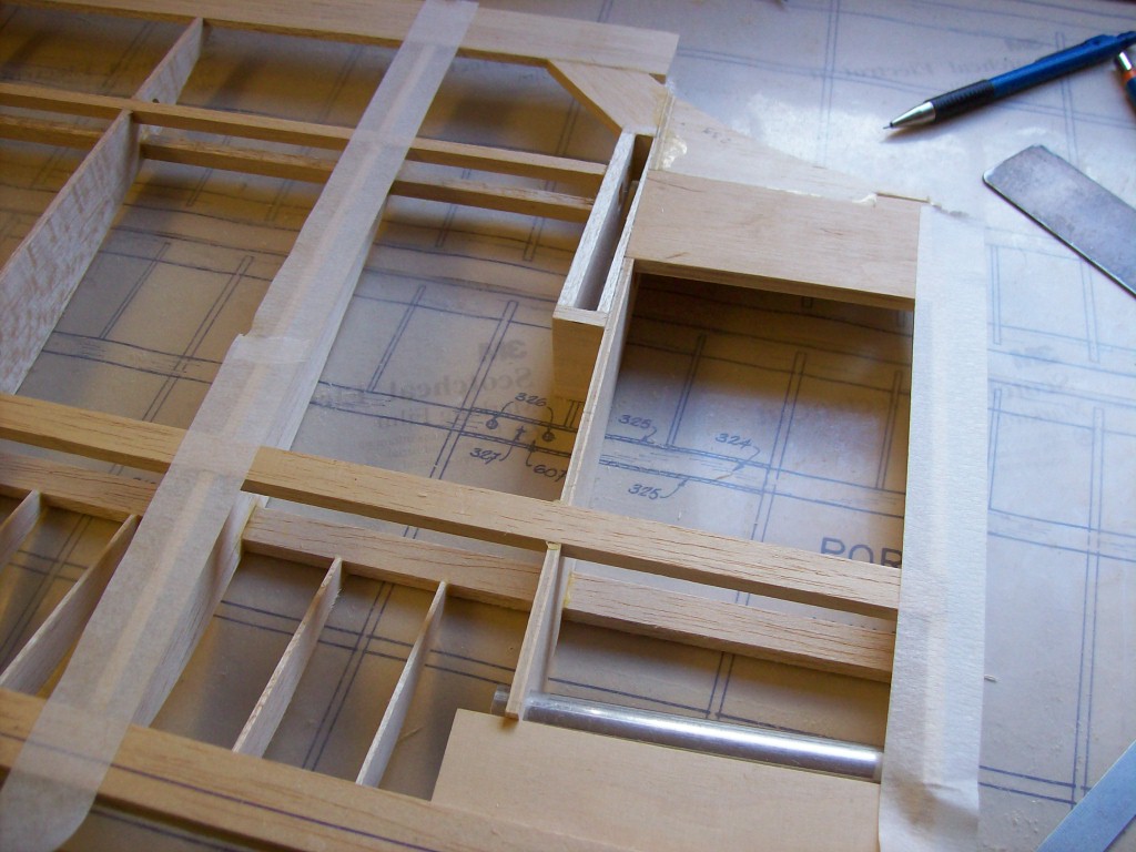
During the sanding process I could see a problem area around the centre section. As can be seen from the above picture. The fabric would have struggled to blend nicely from the centre section block to the trailing edge. The answer was to add a further block of balsa and sand it to shape. This would act a 'land' for the fabric to fix to and to hold the shape along the curved cut-out of the centre section.


Additional balsa block glued in place.


 Balsa block after sanding, still requires a small amount of filler to finish.


 Using the finished panel as a template to mark up the next panel.


Each aileron tip section of the rebate needed filling in with balsa wood, the carbon fibre torque tube would then butt up against this block when finished. This infill is required so as to obtain the top and bottom aileron tip taper.


 Aileron tip before fitting balsa infill.


Aileron tip after fitting the balsa infill, this was sanded flush when dry.


 Planing down the the aileron leading edge.

The aileron leading edge was then planed down, taking care not to damage any wing ribs. The leading and trailing edges were then sanded down using masking tape to prevent sanding down the aileron ribs.

Tape applied to the ailerons to prevent sanding down the ribs.


Aileron tip tapers and trailing edge marked up ready to be sanded to shape.


 Sanding the wing tip taper, underside of starboard wing.

When I had finished sanding down both of the wingtip tapered supports top and bottom I moved on to the wingtips.

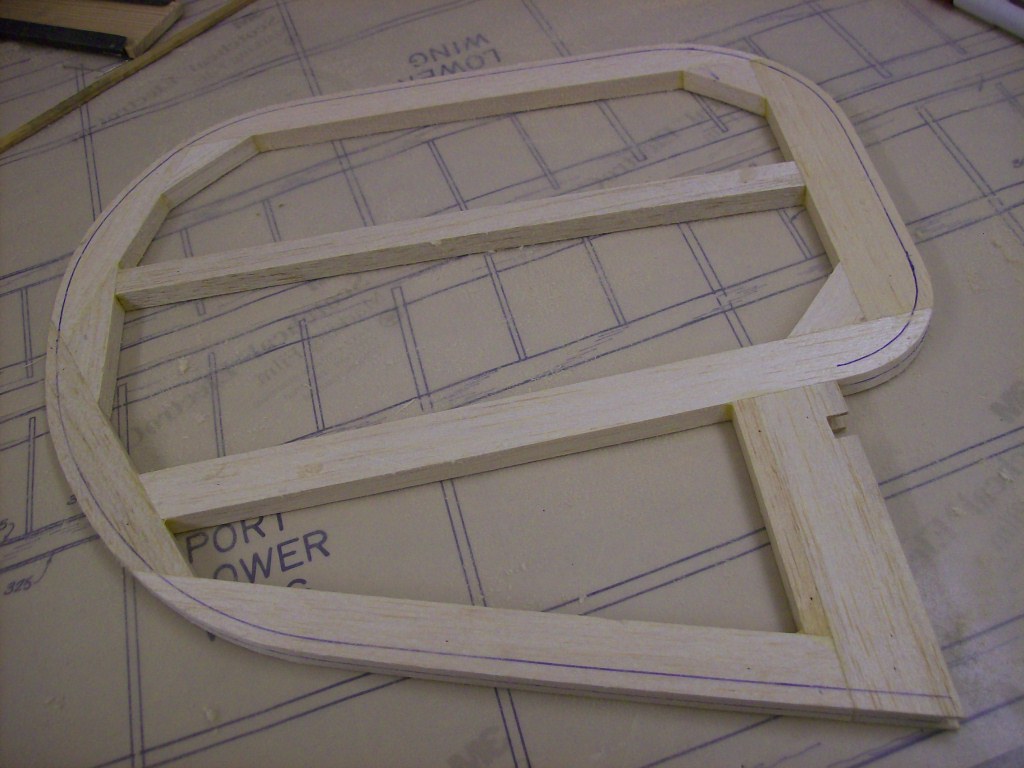
Wingtips are always a bit of an anomaly and the drawings can only show you so much. Wingtip sections are always welcome and the more you have on a drawing then all the better. So interpret the drawings as best you can, decide your plan of attack and stick to it. It helps if you can work the 2 together, this will help keep them looking the same during construction.

With this Nieuport kit the wingtips to the bottom wings are the easiest type to make as you can see from my earlier post but the top wing is a little trickier. So I hope you will find the following pictures showing my interpretation of the wingtips useful. But remember it's only my interpretation of what I deem right. Just try and achieve a nice flowing curve from leading edge to trailing edge and that will be fine.


The before picture, as you can see it looks a little odd at this stage.


And..  the after picture, now we just need to get the starboard tip to match!


Closeup on wingtip, front section.

Closeup of wingtip, aileron section.


In the next post I will be planing and sanding to shape the lower wings.


To be continued...

Workshop Tip No. 4
When you need to sand down a 'high spot' it is sometimes possible to apply masking tape to either side of the 'high spot'. The masking tape will allow the sanding block to pass over the taped area but sand down the 'high spot'. If you sand through the tape before you have finished then remove the tape and apply a new piece.

This method can also be used if you are reinforcing the centre section of a polystyrene and wood veneer covered wing with either epoxy or polyester resin and glass cloth. Apply the masking tape to either side of the finished glassed area then sand it down. The tape will protect the surface, if you sand  through the tape remove it and apply a new piece. The last thing you want to do is sand down the thin wood veneer as it will greatly reduce the strength of the wing around that area of the centre section. The main reason for glassing the centre section in the first place is to reinforce this high stressed area, this will be greatly impaired if you sand down the wood veneer to either side.

Sunday, 5 June 2011

Planing and Sanding

Workshop Tip No. 3
When shaping a piece of wood, whenever possible, sand or plane down to a line. Lines are best applied with a ballpoint pen as  they tend not to indent the surface like a pencil and can be easily removed with fine abrasive paper. Remember work to a line.

It is very easy to get carried away whilst happily listening to that therapeutic sound of wood-shavings parting company with your latest creation, but bear in mind  the difficulty off putting those shavings back after planing away too much!!

Planing to a line alleviates this problem as it is easy to see how much wood has been taken off and how much is left to come off.

Nieuport Build Part 7 - Tailplane Construction and Hinge Detail

The construction of the rudder, stabilizer and elevators are made mostly from 25 mm  X  9mm stock balsa wood strip. After checking the contents of the kit box several times it became apparent that most of this wood was absent!! (NOTE: This wood was taken from the kit by me and used for something else many years ago. It was, however, originally supplied with the kit) Fortunately I had some balsa sheet stock of the right thickness so I cut some strips on the circular saw. I also cut all the gussets noting the direction of the grain. These gussets were all cut at 90 degrees and would be cut and sanded to the correct size on installation.

I started by cutting the balsa strip to approximate lengths and laid them in place over the plan. All the angles were then cut for the outline of each component, rudder, stabilizer and elevators.


 Material cut to approximate lengths,
the curved parts were supplied with the kit.


Material cut to approximate lengths for stabilizer and elevators.


Stabilizer and elevator components glued together.
All the end grain wood was 'pre-glued'.


The above picture shows the elevator components assembled with all the gussets trimmed and glued in placed. The elevator leading edges have been rebated in the same way as the aileron rebates. But this time the rebate was narrower to accommodate a smaller diameter carbon fibre torque tube. The torque tube can also be seen as it was placed in the rebate to align the elevators during the build. After these parts were left to dry overnight  the outline curves were drawn on then cut to shape and sanded at right angles ready for the next stage, planing and sanding the edges to a semicircular section around the outside shape. The trialing edge of the stabilizer and the rebated section of the elevators were left square.


Closeup of elevator torque tube, used to align the components.


Rudder shown assembled and glued together.
The lower hinged section of the rudder was
also rebated to allow for a torque tube to be fitted.


Closeup of rudder rebate.

In the above picture you can see the rebate in the vertical hinge post. Also visible is a circular hole in the horizontal balsa strip at the top end of the hinge post. The carbon fibre tube fits in the rebate and extends into this hole to help support the rudder when it is finally fitted to the sternpost.


Rudder removed from the plan and ready for sanding to finished profile.


Stabilizer and elevators removed from the plan
ready for sanding to finished profile.


A good way of sanding these components flat is to stick down a piece of abrasive paper with double sided sticky tape to a flat surface, block-board  would suffice or better still as I do a sheet of 10 mm thick plate-glass. The part to be sanded is then rubbed over the abrasive paper in a circular motion until you are happy with the result. Don't get carried away though, it's easy to sand off the wood but a lot harder to put the wood dust back!!

Next, using a ballpoint pen I marked around the perimeter of the tailplane components that require sanding to a semicircular section, remembering to leave the elevator leading edges square. Also the entire rudder outline was sanded to a similar semicircular section.


Marking the edges ready for planing and sanding to profile.


The pen is held between thumb and index finger, and the middle finger and ring finger are pressed against the side of the wood then drawn from one end to the other. This enables a pen line to be drawn onto the surface parallel the edge of  the wood, this technique has been used by carpenters for centuries. This line is drawn centrally to each edge that requires sanding. You  then mark the top and bottom of the structure in the same way. The distance the line comes in from the edge is equal to half the thickness of the stock wood used during construction. So if the wood was 9 mm thick then the line drawn on the top and bottom surfaces would be approximately 4.5 mm from the edge.


Workshop Tip No. 3
When shaping a piece of wood, whenever possible, sand or plane down to a line. Lines are best applied with a ballpoint pen as  they tend not to indent the surface like a pencil and can be easily removed with fine abrasive paper. Remember work to a line.

It is very easy to get carried away whilst happily listening to that therapeutic sound of wood-shavings parting company with your latest creation, but bear in mind  the difficulty off putting those shavings back after planing away too much!!

Planing to a line alleviates this problem as it is easy to see how much wood has been taken off and how much is left to come off.


Stabilizer and elevators marked up ready for shaping.

The stabilizer and elevators have been marked up ready for planing and sanding to shape. Also the hinge retaining strap apertures have been positioned and cut out. The carbon fibre tube will be cut to length later. The picture below shows the rudder marked up using the same process as above, the hinge strap aperture has also been cut out.


Rudder marked up and ready for shaping.

Next we plane down the edges to the straight grain areas and sand down those on the curves so as not to 'pull up'  the grain whilst planing. After planing the shape was first roughed out using a coarse sanding block then made smooth using a fine sanding block.


 Planing and sanding to section.
Planing and sanding to section.


Having the line to plane and sand to helps control the shape. If you plane or sand away the line then you know the shape is deviating. When the profiling was complete the pen line was carefully sanded off.

  Pen line being sanded off.


With the components finished and sanded to shape I moved on to the hinge detail. I machined a piece of wood to the required section and cut it into short lengths.


 Wood section used for the hinge bearing packers.


 Hinge bearing packer section cut to length.


The stabilizer leading edge was then marked up ready to accept the 4 hinge bearing packers. These cut outs were aligned with the previously cut apertures for the hinge retaining straps. With the cut outs finished the hinge bearing packers were glued in position.


Hinge components less hinge strap.


The apertures were cut into the stabilizer and the hinge bearing packers glued in place. The hinge straps wrap around the carbon fibre tube and then each strap is nut & bolted to the hinge bearing packers.The carbon fibre tube rotates freely inside the hinge strap.


 This picture shows the 4 hinge bearing packers
in position prior to gluing in place.


The hinge straps were then made from strips of aluminium, cut to length and formed around the carbon fibre tube. Holes were drilled in the hinge straps, top and bottom. The hinge strap was then placed over the wooden bearing packer and drilled through, half way from  the top and half way from the bottom. Drilling the holes this way prevents the drill from wandering and missing the exit hole in the bottom hinge strap.


Closeup of hinge components.


The above picture shows a closeup of the stabilizer leading edge with the hinge bearing packer in place. The hinge strap fits around the carbon fibre tube then is nut & bolted to the hinge bearing packer allowing the tube to move freely. The elevator, seen in the bottom right of the picture above, will eventually be glued in place with epoxy to the carbon fibre tube. Note that the hinge strap cut out in the elevator has been reinforced with thin cyanoacrylate.


 Closeup of hinge detail with elevator removed.


 Closeup of hinge detail with elevator fitted.


Finished stabilizer and elevators with hinges fitted.


Rudder closeup with carbon fibre tube 'dry fitted'.
Rudder has also been sanded to shape in the same manner
as the stabilizer and elevators, cut out for hinge strap also shown.


Closeup of carbon fibre tube and hinge strap cut out.


In the next post I will be sanding and shaping the top wings.


To be continued...


Thursday, 2 June 2011

Removing Pins

Workshop Tip No. 2
When removing pins from a finished wooden structure care should be taken whilst pulling them out.

Always hold down the structure around the area of the pin so it does not pull up the wood and crack a joint.

If a pin has been put though a glued joint the pin inevitably drags glue into the second piece of wood whilst being hammered into the building board and when the glue dries it also glues the pin into the second piece of wood. In  this instance make sure you twist the pin before you pull it out, this will break the glue around the pin. Again hold down the structure around the pin to prevent the structure lifting and cracking a joint.

Nieuport Build Part 6 - Lower Wing Construction

Whilst the top wings were drying (after gluing in place the bell-crank boxes etc.) I started work on the lower wing panels. The top wing panels require sanding and shaping, rigging brackets and plates gluing in position and other items to finish, I'll get round to those later. But first back to the construction of the lower wing panels.

I had to cut up the plans again (I really don't like doing that) to speed up the build and so that I could construct the port and starboard lower wing panels at the same time, this task was done to the right hand side of the work bench. On the left hand side of the bench the plans were cut again, again so that all of the tailplane components could be laid out at once and constructed along with the lower wing panels.

I started construction on the wing panels first by making sure ALL the wing rib cut-outs fit the spars, leading edge and trailing edge material.

  
 The wing ribs being pre-fit to the spars, leading and trailing edges. 


The main problem that I could foresee with these wing ribs were  the 2 thick balsa root ribs. These ribs lean over at quite and acute angle and the ones supplied with the kit were cut at 90 degrees so I re-cut these to the correct angle.
 
Having these ribs cut at the correct angle allows the top plywood centre section sheeting to sit tightly against the top surface of each rib and the bottom angle of the rib allows the fabric covering to also adhere tightly against the rib surface.


   The angle is quite apparent compared to the kit version on the tight.


The next stage was to pin down the leading edge, pinning first one end  then the other and placing a straight edge between the two ends and pushing the centre of the leading edge up tight against the straight edge to ensure the wood was free from curves, the centre was then pinned in place.


Leading edge pinned down and the ribs ready to be glued in place.


After pinning the leading edge in place I pinned down a piece of scrap wood to ensure the spars, leading edge and trailing edge were all correctly aligned. This makes the task of fitting the wing tip that much easier.


Scrap wood used to align spars etc.
This picture also shows some of the components glued in place.


  Setting the root rib angle with a plastic template.

 
  Root rib comparison - 90 degree cut and angle cut.


The above picture shows the difference between the 90 degree cut root rib compared to the revised rib cut with an angle. It would not have been possible to sand down the kit supplied ribs as they would have ended up being much too low in profile and not the same height as the other wing ribs, noticeably so.  


 Port lower wing panel under construction.


Part finished lower wing panels.

When dry the lower wing panels can be removed and all the remaining work can be undertaken without pinning the panels back to the plan. At  this stage the plywood webbing between the spars, the area where the steel bracing plates bolt to, has only been fixed to one side. The captive nuts have not yet been installed. The holes will be drilled and captive nuts fitted after the brackets have been made. I will then use the finished brackets as a hole drilling template, this will ensure perfect alignment of the holes, and all brackets will be marked so they can be put back in the same place during final assembly.

All  the riblets have also been 'thoroughly' glued into position as we don't want them breaking away from the main structure after covering. Again make sure you 'pre-glue' all the end grain joints. 


 Closeup showing plywood webbing glued in place.
A second plywood web will be glued to the other
side after the installation of the captive nuts.


Next, the wingtips can be fitted. These items are both made up of 3 pieces of 4 mm thick balsa sheet that require gluing together and trimming to shape. They need to be made a little longer than shown on the plane so as to allow for  the curvature of the finished wing tip, about 5 mm will suffice. After making the 2 wingtip blanks fit the 4 lower wingtip supports 2 to each wingtip. They extend from the front and rear spars. These pieces also require a slight angle sanding to the top surface to allow for the curve of the wingtip. I used cyanoacrylate for these bottom supports so I could forge ahead with the wingtip construction, for the remainder I used wood glue.


 Wingtip blanks - cut oversize in length.


 2 bottom supports glued in place and sanded to the
appropriate angles to allow for wingtip curvature - port wing.


 'dry-fitting' the wing tips.
Note the direction of the grain - running perpendicular to the tip rib.


After fixing the bottom supports in place the wingtips were glued to them with wood glue and the top supports (4 in total) were then glued and pinned in place and their bottom edges sanded to a slight angle to allow for the tip curvature as before. There were also 4 leading edge tip blocks fitted, 2 to each tip, 1 on the top and 1 on the bottom. Whist the glue was drying the tapers were marked on the tip supports, these will be trimmed and sanded later.

The underside of wingtip glued in place with leading
edge tip block also shown - starboard wing


 The topside of wingtip glued in place with leading
edge tip block shown - starboard wing.

  
 Whilst the glue was setting I marked the 'taper' lines
to the top and bottom tip supports.

At this stage I have not fitted the brass tubes that hold the piano wire wing attachment rods. The fuselage has already been built and the wing attachment brass tubes already fitted into the fuselage. The lower wing plywood facing root ribs will be checked against the fuselage wing attachment tubes first.  If the fuselage tubes align correctly with the holes in the plywood facing root ribs then they will be glued in place on the lower wing panels. The existing holes in the plywood facing root ribs can then be drilled through the balsa wood root rib. The lower wing panels can then be fitted one at a time to the fuselage checking the dihedral as you line up the brass tubes on  the second balsa wood rib. When the second tube hole is positioned correctly the second hole can be marked and drilled out.

When the 4 wing attachment brass tubes have been 'dry fitted'  in both lower wing panels and the dihedral is correct then the tubes will be glued in place with epoxy. There are also 8 square  plywood reinforcement plates that have to be glued to all the wing ribs that the brass tubes fit through. I will post pictures of this stage when I get there, but that's the gist of it.  


Workshop Tip No. 2
When removing pins from a finished wooden structure care should be taken whilst pulling them out.

Always hold down the structure around the area of the pin so it does not pull up the wood and crack a joint.

If a pin has been put though a glued joint the pin inevitably drags glue into the second piece of wood whilst being hammered into the building board and when the glue dries it also glues the pin into the second piece of wood. In  this instance make sure you twist the pin before you pull it out, this will break the glue around the pin. Again hold down the structure around the pin to prevent the structure lifting and cracking a joint.


After fitting the wingtips the lower wing panels were put aside to dry and I moved on to the construction of the tailplane components.


The next post will cover the tailplane construction and hinge detail


To be continued...