Tuesday, 20 September 2011

Dummy Rotary Engine Kit - Part 2 - The DB 1/4 Scale Bleriot

My obvious choice of dummy engine kit for the DB Bleriot would be the one supplied by Arizona Model Aircrafters. it was their version of a Gnome engine kit and it had the correct number of cylinders. Had I used one of the other kits in stock it would have been necessary to remake the crankcase and change the number of cylinders.

The kit included a 'detail' set laser cut from clear acrylic sheet. The intention with this set was to 'super' detail the cylinder heads. There was, however, some discrepancies with the laser cutting, insufficient holes and some in the wrong place. Also some of the laser cut acrylic discs were way too large a diameter and would not fit into the tops of the supplied Williams cylinders. So the decision was made to run with the injection moulded cylinders and cylinder heads from Williams and discard the acrylic sheet. I say 'discard' but like every true model maker you keep it safe as it will almost certainly get used for something at a later stage.

The objective with this exercise was to make a convincing dummy engine quickly and not get too bogged down with making things fit and sourcing additional items when the Williams moulded parts were more than adequate.


Discarded laser cut acrylic sheet.

The first job was to make sure all the moulded components were present and correct.


Components ready for assembly.


Satisfied that all the parts were present,  the 2 halves of each cylinder were sanded flat, 14 in total. This was done using the plate glass sheet with abrasive paper stuck to it. Then any 'flashing' on the moulded parts was removed.

Sanding the parts to achieve a 'good' fit 
Next the 2 halves of each cylinder were glued together and spark plugs fitted. These parts are 'handed' and each cylinder when glued together should have only 'one' area for fixing the spark plug to.

Cylinders glued together and spark plugs fitted.

The cylinders required opening up to allow the cylinder heads to fit correctly. Again these parts are 'handed' when assembled. When looking at the engine from the front the push rods should also be facing towards the front and the spark plug should be on the left.

Cylinders with heads fitted.


Workshop Tip No. 10 
There are many kinds of glue available for sticking together 'polystyrene' or 'ASB' plastic commonly found in injection moulded kits. The traditional 'polystyrene cement', 'liquid polystyrene cement' and 'model cement pens' are OK, but they all leave 'glue' between the two surfaces being fixed together to a greater or lesser extent. These glues should be applied sparingly so as not to look unsightly.

My preference are 'solvent' glues such as 'plastic weld'. This product actually welds together the two surfaces and doesn't leave a 'glue' build-up as any excesses solvent quickly evaporates. Also capillary action 'wicks' the solvent around the joint distributing the solvent producing a continuous weld. Make sure you follow the manufactures guidelines when using solvent or polystyrene glues.

A selection of 'plastic' glue, cement, solvent.

You can also use solvent glue to stick vacuum formed parts to different kinds of wood. Simply 'wet' the area of the vacuum formed part with solvent that comes into contact with the wood and apply solvent to the wood also, this prevents the wood from absorbing the solvent applied to the plastic before it has time to do its job. Then before the solvent evaporate press the vacuumed formed part firmly onto the surface of the wood. The solvent melts the surface of the vacuum formed part and this melted plastic is transferred to the surface of the wood. This can produce a very good bond when done correctly. Practice first on a scrap piece of vacuum formed material and make sure your solvent has melted the surface of the plastic sufficiently.

All the wooden parts are laser cut and require removing from the waste. Once this has been done it will be apparent that there are many duplicate parts. These additional parts are included to allow the builder to adapt the crankcase depth to hide the working engine or electric motor.


Laser-cut parts removed from the waste.

I had to make a small modification to the crankcase sides as  the 'cut-outs' were too shallow. This was easily undertake by cutting down the thickness of the lugs on the crankcase side pieces.

2 of the crankcase side pieces, modified lug shown on the bottom.


This is how  a typical crankcase side part fit before and after the simple modification.

Before, part is standing proud of the crankcase ring.


After, part is flush with the crankcase ring.

Next each side part had a chamfer sanded to both of the long edges, this allows them to fit tightly together. The angle of the chamfer is not critical and any gaps left on the reverse will be filled with glue later. I glued 3 side parts to the crankcase ring with cyanoacrylate first to hold the shape, the remainder were glued in with wood glue, I'm not a great fan of cyano!


The initial side parts glued to the crankcase ring.


Chamfered parts can be clearly seen in this shot.


Part finished crankcase with all side pieces fitted.

The Gnome engine drawing seen under the part finished crankcase is for reference. This drawing has been enlarged to the correct size for the 1/4 scale DB Bleriot . The square outline drawn around the engine indicates the available space within the fuselage and any part of the dummy engine that crosses this outline with have to be removed. This indicated that 3 cylinders would have to be cut down slightly.

After the part finished crankcase had dried the cylinder surround pieces were glued in place, one to the front and one to the back for each cylinder. To ensure a tight fit around each cylinder all the cylinder surround pieces were glued in place to the front first. Then each cylinder in turn was placed up against the front surround piece and the rear piece added.


The last cylinder surround piece being glued in place.

Having got this far most of the build is finished. Remember the construction will be tailored to your individual requirements, engine chosen etc. In my case this dummy engine was to replace the original power-plant altogether.

These were the finished components that made up my dummy engine. Additional parts were added to the rear to enable the whole engine to utilize the same bolt holes that the RCV 120 engine used and to take up the same distance fore and aft. A bulkhead 'packer' with be added to achieve this fore and aft requirement. This 'packer' is not shown in the picture below but will be included later.


The finished engine components.
The nut and bolt are to retain the scale propeller.


The next post will see the engine components assembled, painted and installed it to the Bleriot. A scale propeller will then be made in a future post.

To be continued...

Solvent Glue

Workshop Tip No. 10 
There are many kinds of glue available for sticking together 'polystyrene' or 'ASB' plastic commonly found in injection moulded kits. The traditional 'polystyrene cement', 'liquid polystyrene cement' and 'model cement pens' are OK, but they all leave 'glue' between the two surfaces being fixed together to a greater or lesser extent. These glues should be applied sparingly so as not to look unsightly.

My preference are 'solvent' glues such as 'plastic weld'. This product actually welds together the two surfaces and doesn't leave a 'glue' build-up as any excesses solvent quickly evaporates. Also capillary action 'wicks' the solvent around the joint distributing the solvent producing a continuous weld. Make sure you follow the manufactures guidelines when using solvent or polystyrene glues. 

A selection of 'plastic' glue, cement, solvent.

You can also use solvent glue to stick vacuum formed parts to different kinds of wood. Simply 'wet' the area of the vacuum formed part with solvent that comes into contact with the wood and apply solvent to the wood also, this prevents the wood from absorbing the solvent applied to the plastic before it has time to do its job. Then before the solvent evaporate press the vacuumed formed part firmly onto the surface of the wood. The solvent melts the surface of the vacuum formed part and this melted plastic is transferred to the surface of the wood. This can produce a very good bond when done correctly. Practice first on a scrap piece of vacuum formed material and make sure your solvent has melted the surface of the plastic sufficiently.

Monday, 12 September 2011

Dummy Rotary Engine Kit - Part 1 - The DB 1/4 Scale Bleriot

The process of selling our house is occupying more of my time than I had anticipated and other more enjoyable pastimes have had to go onto a back-burner. But... things are now returning to some form of normality and blogging will commence once again :)

So on that note here is how the dummy radial engine progressed for the DB 1/4 Scale Bleriot.

The pending move to the US has meant the reduction of model related items, leaving only an absolute minimum of paraphernalia to ship, so...alas the Bleriot is just one of many aircraft that I have reluctantly parted with :(( But on the up side it is going to a good home and will spend its foreseeable future on display, hanging from a ceiling somewhere.

The engine in this particular Bleriot was the 7 cylinder 50HP Gnome Rotary, hence the side cheeks to allow  the engine to rotate freely within the fuselage.


 DB Bleriot with RCV120 up front prior to installing the
dummy engine and propeller. One of the side cheeks is clearly visible.

The new owner of the Bleriot wants a dummy engine and propeller fitting so this work was duly undertaken. 

I thought I'd show you some of the dummy engine kits that I have in stock. There are many others available and mine are just a selection of whats out there.

 I have 2 supplied by Arizona Model Aircrafters of the USA. One is the 7 Cylinder Rotary Gnome and the other a 9 Cylinder Rotary Le Rhone or Gnome.These kits are OK but you have to supply your own nuts, washers, bolts, screws, wire and tubing. Sourcing these additional items can slow up the built time whilst you find appropriate fixings etc. But with  their inclusion of laser-cut acrylic components you can add extra detail to areas such as the cylinder heads and manifold pipes. Some of the cylinders, heads and push-rods supplied with the Arizona kits are manufactured by Williams Bros. and some cylinders they have machined to profile from plastic tubing and the heads are from laser-cut acrylic and the builder supplies the metal push-rods etc.


 Arizona 7 cylinder Gnome - 1/4 Scale.


Arizona 9 cylinder Le Rhone or Gnome - 1/4 Scale.


Then there are the Williams Bros. Rotary Engine Kits. These kits are excellent and really do look the part when completed. However, the Bleriot is 1/4 scale and Williams don't do a 'full' rotary engine kit at this size but they do supply the cylinder heads. So that just leaves the model maker to make up a crankcase and fit the 'off the shelf' cylinder heads and 'job done'


 William Bros. 9 Cylinder Le Rhone Rotary Engine Kit - 1/6 Scale.


The other rotary engine kits I have in stock and have often used are made by Mick Reeves Models from the UK. They represent good value for money and they are 'very' complete leaving nothing for the builder to source. So all you have to do is follow his instruction sheet and you'll soon have a very convincing dummy engine to install into your latest model.


 Mick Reeves 9 Cylinder Le Rhone Rotary Engine Kit - 1/4 Scale
can be converted to the Gnome Rotary Engine.


 Mick Reeves 9 Cylinder Clerget Rotary Engine Kit - 1/3 Scale
This one will be going into the Nieuport 17bis.


Here is a completed Mick Reeves Clerget Engine Kit that I made for a 1/4 scale Sopwith Pup. As you can see it looks quite convincing when complete. I will include details on painting and detailing the Bleriot finished engine kit later.

Close-up of engine and aluminium cowl.


Complete engine showing push-rods and spark plug detail.
Close-up of crankcase, cylinder and push-rods.
Reverse of engine showing construction.


Finished engine behind  the aluminium cowl.
The rivet detail and 'engine turning' was also added to the cowl.


The chosen engine will be the Arizona 1/4 scale kit of the 7 cylinder Gnome rotary. I will show the build in the next post.


To be continued...

Thursday, 11 August 2011

Break Over, Back to Blogging...

Sorry for the temporary intermission of the Nieuport 17bis Build. My wife and I are in the process of selling our house which has required more attention and tweaking and therefore less time for Blogging (and building)! Hopefully once I put the finishing touches on the house I can throw myself back into model making again!

I will update later this weekend with a selection of dummy radial engine kits. I hope to use 2 of  these engine kits, 1 in the Nieuport and 1 in the Bleriot. I'll also aim to include details for the dummy scale Bleriot propeller 'kit'

Sunday, 31 July 2011

Nieuport Build Part 15 - Finishing the Top Wing Centre Section - Part 2

The top wing panels are almost ready for the .8mm plywood centre section sheeting to be applied, but first the aileron bell-cranks have to be pinned to the torque tubes with metal dowels. 

The carbon fibre torque tubes had been marked up when they were cut to the correct length in the last post. 

The first stage was to drill a 2mm diameter hole in the end of each carbon fibre tube so that the hole was on the centre line of the aileron box when the tube was fitted. This would allow the bell-cranks to sit centrally within the aileron box when finished. 

2 dowels 15mm long were cut from piano wire and the ends were filed to a 45 degree angle to act as a 'lead'. This 'lead' makes locating each dowel through the holes in the torque tubes much easier.


Torque tubes, metal dowels and bell-cranks.


The metal dowels were placed through the holes in the torque tubes and then the bell-cranks slid onto the tubes until they sat up against the metal dowels.


Bell-crank, metal dowel and torque on wooden blocks.


Each torque tube, dowel and bell-crank was then packed up onto 2 wooden blocks to clear the end of the tube whilst the position of the dowel was marked onto the surface of the bell-crank with a scriber.


Both bell-cranks were marked up as shown above.


After the bell-cranks had been marked up they were cut out with a fret-saw and filed to size so as to obtain the correct fit.


 Bell-crank with metal dowel fitted.


The main components, bell-crank with cut-out, dowel and tube.


The 2 finished bell-cranks and torque tubes with
metal dowels fitted. Not glued together at this stage.


Now that the bell-cranks are finished the 'scale' spar detail can be permanently glued in place. The 'scale spar passes through the rear openings in the centre section. The holes were opened up slightly so that  the spars would be a good fit.


The 'scale' spar passed through the large
rectangular hole to the rear of the centre section.


The 'scale' spar, torque tube and
aileron bell-crank prior to installation.


Next the 'scale' spars were glued in place between the existing rear wing spars either side of the aileron boxes. At the same time the bell-cranks were also installed.


'Scale' spar in place with bell-crank fitted.
The torque tube is also visible but NOT glued in place at this stage.


The 2 'Scale' spars and bell-cranks fitted.
Again the torque tubes are visible but NOT glued in yet.


Now... the .8mm plywood centre section sheeting can be fitted...at last!! This sheeting has already been pre fitted and cut exact to size and the ends sanded to a taper. The plywood sheet was marked and taped into position before gluing the front of the sheet to the leading edge.


Centre section plywood sheeting marked up prior to gluing.
It was taped in place from this point back to the curved centre section cut-out

 
With the sheet held securely in position from the centre to the rear and unable to rotate, it is very important that the sheet does not twist, the front section was left free so that it could be pushed down onto the surface later.  I then applied cyanoacrylate 'kicker' to the front edge of the plywood and medium cyanoacrylate to the leading edge.

The plywood was then pushed firmly down onto the surface of the ribs with a wooden block from the centre to the leading edge where it was held for a moment while the cyanoacrylate set with the aid of the 'kicker'.

The plywood centre section sheeting with the tape removed.

Now that the sheeting was held securely at the front the rest of the sheeting was glued in place with wood glue. Masking tape was used to hold the sheet down until the glue had set, over night.

The rear of the sheet was held firmly in place with 'G' clamps and a wooden block. The block keeps the end of the plywood flat and prevents it from lifting.


Sheeting held in place with tape and 'G' clamps whilst the glue sets.

After the centre section had thoroughly set the 'G' clamps and tape were removed and everything was sanded down. The tapered ends of the plywood sheeting were then blended in with filler at the leading edge and centre section curved cut-out.

As the plywood centre section sheeting is applied to the top of the ribs and no allowance was made for the additional thickness of the ply you create a 'step'. This 'step' will be emphasized when the covering is applied so it's best to 'blend' it into the structure.


Plywood centre section sheeting applied and 'step' created.


It needs to look like this...

To achieve this it will be necessary to add some strips of balsa wood here and there. The 4 pieces of balsa that were glued to each spar, front and rear, were pre sanded to a taper.


There were 7 pieces of balsa cut for each wing panel.
 
The 7 pieces were than glued in place with medium cyanoacrylate for speed then sanded down.

Pieces glued in place prior to sanding.

Sanding the wood down.

To prevent some areas from being sanded down 'masking tape' was applied. And finally the excess 'scale' spar was sawn off and sanded flush with the centre section rib.

 'Scale' spar installed and sanded flush.


The 2 centre sections finished.


The top wing is pretty well complete now. The aileron hinges require installing and the underside of the centre section of both top wing panels require a 'land' making around the front aluminium centre section strut mounting. This 'land' is required for  the covering to adhere to and will be made when the lower wing panels are fitted to the fuselage. I intend to fit the top wings to an inverted  fuselage, as the top wings are flat, then fit 'temporary' interplane struts whilst the lower wing panels are fitted. The wings will be rigged at later stage.

When the interplane struts are made and finished off they will replace the 'temporary' ones used earlier. Once the actual interplane struts are installed the wings can be rigged. However, final tensioning of the rigging wires will be done at a later stage, setting the incidence and washout etc. 

Remember ALL the rigging wires are functional and should NOT be omitted.


To be continued...

Friday, 22 July 2011

Nieuport Build Part 14 - Finishing the Top Wing Centre Section - Part 1

After the top wing panels had been fitted to the fuselage they were removed so that the remaining work could be finished. To be sure that the wing panels retained a good fit at the centre join whilst finishing  them off they would be bolted back together with 2 scrap 6mm thick plywood braces, but first the tubes and .8mm plywood capping were fitted.

The 4 tubes were made rough with coarse abrasive paper so that the epoxy glue would 'key' to the surface.The 2 hardwood dowel 'plugs' were glued in first, these  tubes were marked up 'FRONT' so I didn't stick them in the rear by mistake later.


Wing joining tubes, dowel 'plugs' and epoxy.

Dowel 'plugs' glued in place.

The components of the starboard wing panel less the riblets.

 
The plywood centre section sheeting will not be applied yet until the 'scale' spars have been permanently glued in place. The sheeting has, however, been cut  exact to size and all the short sides have been chamfered. Chamfering the edges now makes blending the plywood into the balsa leading edge and balsa centre section cut-out much easier. If the plywood was applied then blended in you risk the chance of sanding the balsa wood away first before the plywood.

Chamfered plywood before and after.

 
The wing joining tubes and captive nuts were than glued in place with epoxy. The tubes protrude slightly as the plywood capping ribs still require fitting.


Wing joining tubes glued in place and riblets trimmed and ready to fit.

 
The plywood capping and riblets were then glued in place with wood glue. Not forgetting to cut the 2 extra cut-outs to the rear of each capping rib for the 'scale' spars to slide through. Where the riblets touched the aluminium tubes epoxy was used to secure them.


Plywood capping held in place with masking tape while the glue was setting.


To give the plywood centre section sheeting more purchase at the front and to stop the sheet lifting after gluing, it's a good idea to fill in the riblet bays in this area with scrap balsa block.


Balsa block infills will be sanded down later.

Now is a good time to colour the inside of the aileron boxes and the visible section of the 'scale' spar detail. A light oak water based stain was used, light oak being the best colour to replicate 'old pine'.


Aileron box and spar with light oak varnish applied.

The reason for staining the boxes etc now is because the 'scale' spars require gluing in place before the center section sheeting is applied. If the centre section sheeting was applied first you can't get at the spars to glue them in place and these spars are functional.

Also the aileron bell-cranks have to be installed at the same time as the 'scale' spars are glued in. So I best not forget to include those bell-cranks!! I'll cover this in a future post.

Whilst on the subject of ailerons, I also cut the 2 torque tubes to length. These tubes were also marked up on each end so that I would know were to drill the holes for the aileron bell-crank retaining pins, installation details to follow.


Aileron tube being cut to length.


Next the leading edge of centre section was sanded down, this can be done with the wing panels joined together as the wings are flat.


Centre section leading edge sanded down.


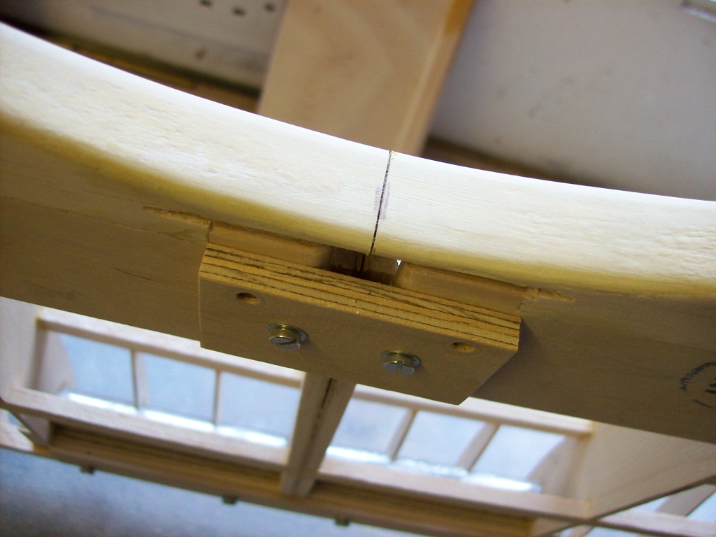
Underside view of the centre section showing temporary plywood joiners.

Also seen in the above picture is a white plastic insert placed into the cut-out for the rear mounting bracket fixing. This plastic insert was there to stop filler from getting in the aperture.

A polyester resin '2 part' wood filler will be used to make good the centre section join. The underside was filled first.


Wood filler applied to the underside of the centre section, the easy one.

 
Then came the top of the centre section. Looking at scale reference this area was more square than round in section and therefore needed 'squaring' off.

The filler was added gradually first to the curved section then to the top section, the edge of the filler was finally sanded to a right angle.


Filler sanded at right angles, port wing panel.

Once the filler had been sanded at right angles the sharp edges were then chamfered. The amount you sand off will be determined by the size of radius you require.

Remember the 'shadow sanding' technique, it can be seen to full effect in the following pictures. The shadows cast clearly show your progress during the shaping process.


Sharpe edge sanded off, note the taper of the chamfer
so as to blend in with the trailing edge.


Both sides chamfered to a uniform shape and confirmed by the shadows cast.

And finally the sharp edges of the chamfers were removed until a 'sweet' curve was achieved.


Chamfers rounded off and final shape finished with fine abrasive paper.

All that needed to be done now was to 'split' the 2 sections on the centre join, currently held together by the wood filler. This was done with the aid of a razor saw.


Razor saw being used to separate the wing panels.


Wing panels after separating.

The next post will see the centre section finished...hopefully

To be continued...