Monday 30 January 2012

David Boddington - 1/4 Scale Bleriot XI B - Photos Part 5 - Rear Cockpit

The following pictures show close-up shots of the rear cockpit. Again, information on the full size Bleriot was hard to find so I used details from other aircraft of the same period.

 
The rear cockpit forward of the seat showing duck-board and control cables.

The grey panel in the picture is the back of the front cockpit bulkhead. The control cables seen passing through this grey panel are for the rudder and elevator controls. The 'duck-board' in the foreground is a foot rest for the pilot. The 2 small tubes coming from the grey panel at the bottom centre are for the 'bomb drop' cable to pass through. The entire area has also been 'dirtied up' a little to give it that 'used' look.

  
Aerial view of rear cockpit.

The plywood seat is similar to that used for the front cockpit but it has been cut down in height. The 'duck-board' can also be seen. The majority of the rear cockpit detail was constructed from 'liteply' and balsa wood to keep the weight down. The leather cockpit trim can also be seen, this is made in the same way as that used for the front cockpit (see Part 4 post for Front Cockpit description) 


Rear cockpit leather trim close-up. 

As the leather trim around the rear cockpit is in a 'U' shape it was necessary to taper each end. This was achieved buy sewing in a dart to obtain the correct taper. This trim was held in place using the same method as that used for the front cockpit, with eyelets and thread. Again, the thread was stained to help it blend in with the 'weathered' fuselage.


Close-up of rear seat. Cross bracing can also be seen.

If you look closely you can see 4 very small 'eye-hooks' on the starboard side of the fuselage under the seat. The receiver aerial wire passed through these 'eye-hooks' to keep the wire in place during flight.


 Another close-up of the rear seat and support. 


Close-up taken under the rear seat showing the dummy reserve fuel
tank in place. The tank was fixed to the front seat rear bulkhead.


The dummy reserve fuel tank filler cap.
The filler cap is situated just behind the front cockpit opening.


Another close-up of the dummy fuel tank,
taken when the model was finished.


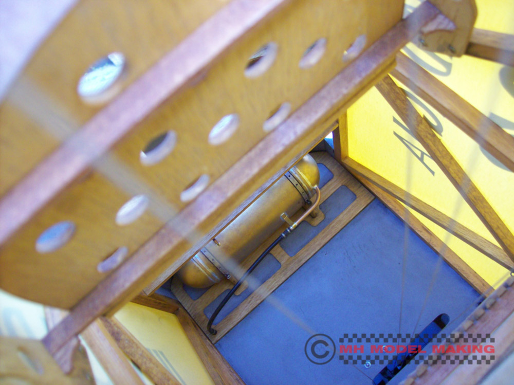
This picture of the dummy fuel tank
was taken before the fuselage sides were covered.


 The finished dummy fuel tank prior to installation. 

The basic construction of the dummy fuel tank was made from .25mm thick plastic card (HIPS - styrene sheet) A tube was rolled to form the centre section of the tank. The domed ends were made using heat and a simple 'plug' former. This method results in a formed part without using a 'vacuum forming' machine.

When the basic construction was finished the tank could be detailed. A thin strip of plastic card was wrapped around each domed end were it joined the centre section tube. This thin strip was to simulate a 'flange'. 

A plastic tube was glued to the top of the dummy fuel tank, this was to attach the filler cap to later, also made from plastic card.The other pipes visible were made from aluminium tube and wire. The support bracket for the large tube at the bottom of the tank was made from very thin aluminium sheet (litho plate). The 'wrap-round' straps that hold the tank to the bulkhead were also fabricated from thin aluminium sheet. Holes were drilled in this strap to add some scale detail and a strip of plastic card painted black represented a 'rubber' gasket between the bracket and tank.

The 'sight tube' to the left of the tank was made from 2 short pieces of aluminium wire bent at right angles. 2 holes were drilled through the tank and the right angled pieces of wire glued in place. After the tank was painted a short length of clear plastic tubing was placed between each piece of wire. The clear tube was also painted inside to give the illusion that there was fuel in the tank and tube.

The finished tank was painted to look like copper and 'weathered' All the seams and bracket fixings etc. were outlined with silver paint so they look like soldered joints. 


Undercarriage photographs to follow...

To be continued...

Friday 13 January 2012

Tirrem Messing About...

It's Friday 13th!
Tirrem's reply to that, "I'm not superstitious, knock wood!"

Tirrem's First Photo Shoot didn't go according to plan... He just had to MESS about and as such, ended up on his FACE!  Ouch, that must have hurt!


I meant to do that!


Wednesday 4 January 2012

David Boddington - 1/4 Scale Bleriot XI B - Photos Part 4 - Front Cockpit

The following pictures show close-up shots of the front cockpit. There wasn't much going on in the pilot's seat of a Bleriot X1 B and instrumentation was a little sparse. In the absence of good documentation some of the details were taken from other aircraft of that era.

Also the David Boddington Bleriot is 'sport scale' and was never intended to be an exact scale model of the original. That said, there is plenty of scope to add scale detail to make the model look very authentic. David was a great believer in 'dirtying up' a finished model as it helps give it that 'used' look, but don't go overboard with the weathering.

 Seat, fuel gauge, control column and fuselage interior can be seen here.

The bracing wires to the fuselage sides were none functional. The actual control cables are visible at the bottom and consist of 2 for the rudder, 2 for the elevator and 2 for the bomb drop.

 
Seat close-up.

I use this style of seat in nearly all of my WW1 planes, they look convincing and only have 3 components to them. I will do a 'blog build' showing how they're made and include PDF templates so you can make your own.

The control column can also be seen, it was 'sprung loaded' and moved fore and aft, left and right. The control column was connected a dummy 'wing warping' control arm under the fuselage via cables. When the column was moved left or right the 'wing warping' control arm would move too.

There was no actual wing warping required to fly the model. Boddo wrote in the instructions that to include wing warping made little to no difference and that the Bleriot flew just as well on rudder and elevator and therefore didn't justify the extra work involved to include a wing warping system.


A close-up of the control column front support pylon.

This pylon was caved from a small block of  basswood using a small electric drill and cutting bit. The base was from plywood and the top 'bush' was made from brass tubing.


This shot clearly shows the leather cockpit trim, brass eyelets and stitching.

The leather used was from an old secondhand jacket that I bought. The leather had to be pared down using a sharp blade to reduce its thickness. The join (two in total) that can be seen was hand stitched from behind and the seams laid flat against the underside. Also included in this trim was a length of rubber tubing, about 5mm or so in diameter. This tubing was stuck to the back of the leather trim along a centre line. The trim was glued to the edge of the cockpit cut out. This took quite a long time and great care has to be taken so as not to get glue on the silver painted fuselage sides.

The eyelets were then added once the spacing had been worked out. I used a 'bradawl' to make small hole for the eyelets to pass through and held them in place with cyanoacrylate. The stitching was added and then stained after completion so as to blend in with the leather trim. If the cockpit trim is exposed to waste fuel and oil it is advisable to use leathercloth as it can be wiped clean, leather will tend to absorb the fuel and oil leaving stains. Eyelets can be obtain from Mike Reeves Models in the UK 


 General picture showing entire cockpit opening.


Close-up showing a dummy box behind the seat.

This above dummy box was hiding the wing retaining tubes. The short length of wire seen on the right-hand side of the box is a dummy reserve fuel line from the auxiliary tank situated in the rear cockpit. Rubber tubing was placed over this wire and connected to a dummy fuel tap situated on the left-hand side of the cockpit towards the front.


 This is the dummy auxiliary fuel cap filler just behind the front cockpit.


 Front deck showing more dummy filler caps.

These are the dummy oil and fuel filler caps to the removable top front decking. The bottom right filler cap was removable.  When this filler cap was removed access could be made to the deck retaining screw.


Here we see the fuel gauge made from plastic card for the casing and
bracket with clear for the glass. Held in place with small screws.


Rear cockpit photographs to follow...  

To be continued...

Saturday 31 December 2011

My 2011 Top Ten Toy List (3TL)


The 3TL Count Down
# 10 Tool Box
This is one cool tool box and present from Erica ... and made to a very high standard too. They will go well in the workshop I plan to build when I get to the US. The attention to detail is superb, although I wish they'd made the pliers move, I feel a modification coming on!


# 9  Tamiya 1/6 Scale Monkey Bike
I've been after one of these for years. This one came up on eBay UK and was a real bargain, another eBay gem and cheap at half the price. It's the 2000 Anniversary Edition with several extra parts for a customized version. The extra parts will make nice props laying around the 1/6 scale workshop. 


# 8 Minichamps Honda CB 750 Four
This was an excellent find from Nortons Trade Only Toy Store in Leicestershire UK that I sometimes go to, I knew having my own business would come in useful some day. The boxed Honda was thrown, and I mean thrown, in a bargain bin. There were about 4 in there and 'super' marked down. I spent some time trying to find the best out of a bad lot and settled on this one. I took it apart so as to repair the bits that had either fallen off or were broken off. I will rebuild it in 2012.


# 7 Folding Chairs
These were a Christmas present from Erica and they are ACE! I have a set of 4 and they are so cool. They'll look great in my planned room sets on hold at present until I get to the US.


# 6  Vespa Scooter 150 VL 1T (1955) by New Ray
Another eBay find but it was badly damaged, smashed to bits to be exact. A total rebuild was undertaken and a change of colour made too, from  the standard white to pale blue. I dismantled every component and repaired all the broken parts, just about everything was damaged. I re-bushed the wheels and held them in place with tiny nylock nuts, they also look more scale like. The seat hand rail was missing and so was the main stand, both were fabricated from K & S stock brass wire and strip. The finished repair was then painted using automotive paint and detail added using a brush


# 5 Tamiya Vintage Honda CB 750 Four Kit
The last time I had this kit I was 12 and have wanted to get another for many years. I didn't want the new version as some of the contents differ from the original 70's kit. The first item to go was the individual metal link chain now it's just a solid plastic offering. This was yet another eBay win and sooooo cheap. It was listed in the wrong category and had been part build and bits were missing, allegedly, but on receipt all the parts were found to be present. It had, however, been painted gold!! It took a very long time to remove the gold paint even with the use of an industrial ultrasonic cleaner. It's now waiting to get built.


# 4 Boots
Another great gift from Erica. These superb boots are just like real ones but tiny! How do they sew them together? we'll probable never know! My guess is they must be using some form of miniaturization machine, I want one!!


# 3 Kayak
Wow, cool or what! Erica found this one too. I was trying to guess what this present was for ages and failed miserably. I came up with all sorts of ideas and none as it turned out were even close. It works a treat and was duly test in a bath if cold water and passed admirably.


#2 Guitar
Double wow with bells on, thanks to Erica again... Just something else made using that miniaturization machine, indistinguishable from the real thing, apart from the size that is.


# 1 Tirrem Mesu
Erica created Tirrem for me after I had asked if I could have a Merritt making. 'No, there will only be ONE Merrit' came the reply. So I came up with Tirrem, Merrit spelt in reverse, pretty good hey!! and  the surname just had to be Mesu : ) I must say he's turned out very well thanks to Erica's creativity. She worked like a demon getting him all finished for Christmas but she came up trumps again.


 Well, that's all folks, I'll keep my eyes open for more toys during 2012...

David Boddington - 1/4 Scale Bleriot XI B - Photos Part 3 - Dummy Engine & Prop

The Bleriot was to be collected soon by its new owner so the Dummy Engine and Propeller needed to be built and fitted before his arrival.

I will be updating my blog with the remainder of the build for the Bleriot Dummy Radial Engine Kit and also the build for the Bleriot Dummy Propeller Kit.

The following pictures show the dummy radial engine and propeller installed into the Bleriot. Remember this dummy engine extends right back to the bulkhead as the plane is now destined for static display only. So if you intend to fit an IC engine behind the dummy radial engine it will be necessary to allow for clearance of the IC engine during the build.


David Boddington - Bleriot XI B Installed Dummy Engine Pic 1 - Taken inside.
The Nieuport 17bis fuselage can be seen in the background.


 David Boddington - Bleriot XI B Installed Dummy Engine Pic 2 - Taken inside.


The propeller hub has 6 dummy nuts & bolts front and rear, they did not pass through the entire hub. The silver 'washers' were made from 'plastic card' (HIPS). One washer to the front and one to the rear. Holes were drilled to each washer to allow the dummy blots to fit through. The finished washers were then painted, weathered and then glued in place. The centre nut was made from a 'cut down' nylock nut. The nut was now a 'quarter nut' with the nylon insert still in the front. This nylon insert retained the propeller on the crankshaft of the dummy engine. In my case the propeller was free turning on the crankshaft bolt and the dummy engine was fixed.


David Boddington - Bleriot XI B Installed Dummy Engine Pic 3 - Taken inside.

 
 David Boddington - Bleriot XI B Installed Dummy Engine Pic 4 - Taken inside. 
  

The next 3 pictures were taken outside and have a better colour to them, a closer match to the actual model (on my screen anyway, hope they are on yours too)


David Boddington - Bleriot XI B Installed Dummy Engine Pic 5 - Taken outside.


 David Boddington - Bleriot XI B Installed Dummy Engine Pic 6 - Taken outside.


 David Boddington - Bleriot XI B Installed Dummy Engine Pic 7 - Taken outside.


Front cockpit photographs to follow...


To be continued...

Wednesday 28 December 2011

David Boddington - 1/4 Scale Bleriot XI B - Photos Part 2 Maiden Flight

After rigging the model in the parking area at the flying field and taking some pictures I wheeled  the Bleriot over to  the pits area and got things ready for the Maiden Flight. I was using a 'Fail Safe System' that would set the engine to idle, the elevator to level and a small amount of rudder. This would cause a slow spiral descent if I were to get any radio interference. I did a 'range check' and 'fail safe check' both with and without the engine running. All was OK so the tank was filled and the engine fired up. The engine speed was checked and I couldn't get the recommended  rpm form  the engine, it fell short by approximately 250 rpm. The pull from the engine at full throttle was considered to be sufficient. This however in practice proved not to be the case!

Final checks were made and having run out of excuses to postpone the flight the tank was topped up, engine started and it was off to the 'patch' for takeoff!

I must have aged about 10 years as the wheels left the ground. The engine was running slightly rich and it was down on the maximum rpm, but it was chocks away and off the Bleriot went!

The Bleriot  took off nicely but it was apparent that the RCV was slightly underpowered, being down on the maximum rpm and the Bleriot was gradually loosing height! As it flew further away it was getting alarmingly low in the sky. A decision had to be made, land it in the direction it was going and hope for the best (bad idea) or turn it back towards the takeoff area. The decision was made to turn the model back towards the take area and 'down wind'. Normally this results in the model losing height but on this occasion it lifted a wing and gained height, thankfully. The wind had considerably picked up by now which created yet another problem, landing. Several approaches were made and aborted with the final approach being made at a steep angle to increase the speed and then flared out for the final touch down and safely back on terra firma.

There is lots of drag from all those rigging wires and  the model, like the real Bleriot flies slightly faster than the stalling speed. The angle of flight was very good with no tendency for the tail to drop as I was assured it would. The only adjustment needed was 2 clicks of down trim on the elevator. This trim was later removed by adjusting the movable stabilizer by 2mm.

Subsequent flights were made but this time using a 20 x 12 APC propeller, expensive at about £25 each but what a difference it made to the thrust. The RCV engine is quite powerful and needed that extra weight that the APC propeller has. For the first flight I used a 20 x 12 lighter wooden propeller and it was not as efficient as the heaver APC propeller. Also the wooden propeller was in fact slipping on the 'prop driver' and on occasion stalling the engine when the throttle was opened fully. When the wooden propeller was removed from the engine the 'prop driver' had cut into  the back of the propeller by 3mm or so!


 Chocks Away...


The point of no return...


After gaining height and settling down the
Bleriot really did look the part in the air.


A nice 'flypast'
The Bleriot is really looking at home in that blue sky.


And finally the inevitable landing!


The days flying went well, the weather was superb, all in all a successful day. The RCV engine ran well and didn't let me or the Bleriot down. The engine eventually ran to is maximum rpm with the APC propeller fitted and was well worth the additional expense. Further takeoffs were achieved without using full throttle as the APC propeller was far more efficient than the wooden propeller used during the maiden flight.
 
Don't forget I will be uploading more photographs of the Bleriot over the next few days so please remember to drop by again for the updates. 


To be continued...

Tuesday 27 December 2011

David Boddington - 1/4 Scale Bleriot XI B - Photos Part 1 - Maiden Flight

After having built the Bleriot over a 2 year period the time came for it to take to the skies! The RCV 120 four stroke had been bench run and was ready to be installed. With the engine and radio control equipment in place the C of G was checked and then re-checked. The plane had to be carefully rigged too. The dihedral was set along with the 'washout'. It is very important to include the washout and to make sure both sides are identical. I had to extend the arms to my incidence meter to span the 559mm cord. When I was satisfied that the rigging was OK all the cable end 'crimps' were made and the model was ready. The rigging wires were then removed from the fuselage pylons and carefully wrapped up and bagged on each wing panel. The rigging time at the field was about about 45 minutes.


The Bleriot in the pits on a glorious sunny day, perfect 'maiden flight'  weather!


The following pictures were taken on the same day. A few general shots of the Bleriot on the ground then some of the Bleriot flying.


 RCV Engine installation - Cowl removed.


Undercarriage - Side view.


Undercarriage - Bottom view.


 Front cockpit showing 1/4 Scale AH Design pilot.

 
Rear cockpit showing seat detail etc.

  Tail skid detail showing bracing wires and pull springs.


Rear of fuselage showing stabilizer, elevator and rudder.

 
Underside showing the 'Bomb Drop' bracket.
The bombs were dropped separately.


The above photographs were taken with a 35mm 'film' camera and the images have been scanned for use here. I will be placing more recent digital photographs on my blog that were taken whilst the plane was at my parents house. I am still living out of boxes, LOTS of boxes, very annoying! So thanks to my parents for letting me keep some of my stuff in their garage.

The digital images show many useful 'close-up' shots, so if you are planning on building the 1/4 scale Bleriot XI B by David Boddington you will hopefully find them helpful.


To be continued...