Wednesday, 25 May 2011

Nieuport Build Part 5 - Top Wing Construction - Continued

Remember those 2 aileron bell-crank boxes, the first items that were made for the top wings, well the time has arrived to glue them into the wing structure. I need to do a little prep work first and one or two 'dry fits' then they're ready to be glued permanently into position. Firstly they both had to be sanded to a taper. I achieved this on my faithful disc sander but a sanding block complete with rough abrasive paper would have had the same result.

 The completed tapers on the 2 aileron bell-crank boxes.


The boxes now have to be fitted into each wing panel. The full size Nieuport had a visible rear wing spar that ran through the aileron bell-crank. The "Boddo's" Nieuport has 2 rear spars and for the addition of the more scale like aileron bell-cranks this would have to be reduced to 1 rear spar. 

The existing rear spars in each wing panel were cut short during construction as previously mentioned to allow for the insertion of the aileron boxes. Then the balsa root ribs and inboard plywood ribs had apertures made between the top and bottom balsa spars to allow for the 'scale' spruce spars to slide in between the spars that were cut short. The spars that were cut short will eventually be glued to the aileron bell-crank boxes and the single rear spruce spars thus giving that area the required strength and rigidity.


Port aileron box detail showing aileron torque tube
and single spruce rear spar. 'dry-fitting'


Plan view of port aileron box detail showing aileron torque
tube and single spruce rear spar. 'dry-fitting'


This shows the port wing component parts, torque tube,
spruce spar and aileron bell-crank box.


Fist I had to cut the apertures in each wing panel between the rear balsa spars for the single spruce spar to fit  through. Cutting the opening in the balsa root rib presented no great problem this cannot, however, be said for  the inboard ply rib. I managed to drill a hole through the plywood rib then had to open it up using a scalpel knife whilst bending the 2 balsa rear spars to one side.


Port wing panel showing opening cut into balsa root rib and the starboard
wing panel marked out ready for the opening to be made.

The reason why these openings were left until now was to keep the wings aligned during the construction stage. The wings were quite fragile after being built around the area of the centre section curved blocks and trailing edge gussets. This will be alleviated when the spruce spars and aileron bell-crank boxes are fitted.


The starboard wing 'weak spot' is shown here. The only part holding
the tailing edge of the wing together from the centre section
block is the triangular balsa gusset.
A good job we 'pre glued' those gusset joints!


 Closeup showing the starboard wing apertures for the single spruce rear spar.
It would have made the construction more difficult had these
apertures been cut before the build started.


Here the starboard wing spruce spar is 'dry fitted' to ensure a good fit.
It still requires trimming to the correct length.


Now we have the spar in place we can start work fitting the aileron box. Remove the spar and 'dry-fit' the aileron box into place, slide the spar in until it touches the aileron box then mark its position with a pencil line, remove spar and box.


Aileron box with spar position marked on and ready for cutting out.

A wooden block was paced inside the box to cut against, remember the box has been sanded to a taper and is very fragile at this stage. I reinforced the tapered joint with thin cyanoacrylate to help keep it in one piece.


Aileron box with spar opening cut out.

Place the aileron box back in to the starboard wing and slide the spruce spar in again and mark the second position of the spar onto the box then remove components and cut out the hole as before, using the block inside the box to cut against.


Spruce spar fitted through aileron box.


 Aileron box and spar 'dry-fitted', now onto the next stage,
fitting the aileron torque tube.

With the aileron boxes in place I sanded the end of the carbon fibre torque tube and slid it through  the holes in each wing rib until it reached the aileron box. The tube was then rotated and the carbon dust on the end of the sanded tube was sufficient to mark the position on the box for cutting out the first hole.


 Carbon tube in place, rotated to mark the position
of the tube for cutting out the first hole


Position of tube marked in place.

Cut out the first hole as before with wooden block inside to cut against, place the aileron box back in the wing and mark the second hole in the same way, remove and cut out the hole.

The aileron box is now finished and ready for gluing in to position.


Wooden 'packers' were put between the two rear spares and inside
the aileron box to keep all the joints tight whilst the glue was setting.


After gluing the boxes in place I moved on to the aileron cut-outs and filled in the gaps between the ribs with balsa wood strip, behind the webbing that the ailerons will be secured to at a later stage.


Before fitting the balsa strip.


After fitting balsa strip.

The top wings can now be put to one side to dry. In the next part I will be making the lower wings.


To be continued...


Friday, 20 May 2011

Pre Gluing End Grain Joints

Workshop Tip No. 1
Remember to pre-glue all end grain joints, this prevents making a 'dry' joint. If you don't when dry the joint appears glued together but if it is subjected to a sudden knock the joint more often then not breaks away from the glued area. This is due to  the applied glue being drawn into the end grain of the wood and leaving very little glue on the surface to make a secure bond, pre-gluing means to apply the glue and work it into the end-grain and wait for it to dry. Once dry sand off any grain that has lifted and glue in place as normal.

Thursday, 19 May 2011

Nieuport Build Part 4 - Top Wing Construction - Continued

In the Nieuport Build Part 3 post the port wing was shown pinned down and parts glued together  but at that stage the starboard wing was only temporarily pinned in position.

The starboard leading edge has since been unpinned and 3 plastic packers placed between the 2 balsa root ribs. These packers temporarily replace the 2 plywood facing root ribs that will be glued to the face of each balsa root rib at a later stage.

The picture below shows rib-lets that have now been added to the port wing. The rib-lets over each wing joining tube will be fitted after the tubes have been glued in place.


This picture shows the 3 plastic packers in place.
Note the 2 gussets from the centre section blocks to the trailing edge
have notches cut in them to allow for the aileron bell-crank boxes to fit correctly.

These packers allow the spars, balsa root ribs and leading edges to be pushed up nice and tight against each other whilst the glue is setting. The glue does not sick to the plastic packers so the 2 wing panels will separate nicely when the construction is complete. The sections are best made together to insure the wing dowels and aluminium tubes line up correctly, note at this stage the aluminium tubes have not been glued in place.

The centre section blocks have also been glued in place after minimal sanding they dropped into position, nice cutting 'boddo', spot on with the plan. The 2 gussets have also been pre-glued then glued in place, note the direction of the grain when making gussets.


 Correct direction for grain when making gussets.


Workshop Tip No. 1
Remember to pre-glue all end grain joints, this prevents making a 'dry' joint. If you don't when dry the joint appears glued together but if it is subjected to a sudden knock the joint more often then not breaks away from the glued area. This is due to  the applied glue being drawn into the end grain of the wood and leaving very little glue on the surface to make a secure bond, pre-gluing means to apply the glue and work it into the end-grain and wait for it to dry. Once dry sand off any grain that has lifted and glue in place as normal.


Centre section front - closeup


centre section rear - closeup


Starboard wing panel with parts glued in place.
 
Here we see the starboard wing panel finished to the same stage as the port wing panel, however, the panels are not  yet complete and still require their wingtips fitting and ailerons making. You can also see from the picture a black tube running through the wing ribs, this was a test fit of the carbon fibre aileron torque tube (the actual tube will be a little longer than that shown). All holes aligned well and the tube moved freely. It is not crucial that the tube is a tight fit in the holes of the balsa wing ribs as the main bearing point for the torque tube is in the plywood wing rib that the aileron bell-crank box is fixed against and the 3 hinge packers glued to the webbing of the aileron cut-out in the wing. 


Both wing panels finished to a stage were they can be removed
from the workbench, sanded to shape and other
parts glued in place to complete the wing at a later stage.

I have been looking for the pictures I thought I had taken with regards to the construction of the ailerons and wingtips but alas it would appear that I have none!! Just pictures of the finished items but I do have pictures showing the tips and aileron prior to trimming and sanding to shape.

The ailerons are very straightforward and only have a few parts to them. Again, I made sure that all the ribs were pre-fit to the tailing edges and that the ribs were numbered so as they could be easily identified when needed as the aileron gets wider towards the tip.

The aileron leading edge was different to that supplied with the kit and mine was cut from 13mm thick sheet balsa with a rebate cut in the front edge. The rebate was deep enough to allow about 2mm of the tube to protrude from the front face.


Carbon fibre tube and rebated section off-cut.

This protrusion and spruce hinge packer that the tube is fixed against with the 'U' shaped wire retainers will give the required gap to the leading edge of the aileron when installed. So this gap was achieved  whilst building the aileron by using plastic packers along with the carbon fibre  tube inserted through the holes in the balsa wing ribs, ply wing ribs in the centre section and into the aileron rebate and pinned in place. The gap to the inboard end of each aileron was also achieved with a plastic packer.

The finished aileron and wing panel removed from the plan.
The aileron and wing panel still requires planing and sanding to shape.

Before I removed the wing panels and ailerons from the workbench the wing tips were added. The wing tips were made from hard 25mm wide x 4mm thick balsa sheet. The curve was achieved by holding the wood fast in one hand and gripping firmly between thumb and four finger with the other hand. Then move the thumb and four finger from the hand holding the wood fast towards the free end whilst moving though an upward curve. Keep doing this until the desired curve is obtained.

There is sufficient information on the drawing to determine the height of each tip packer that is fixed to each spar extension and supports the tip top and bottom and holds the curve in place. The packers were glued in pace to the bottom spars first then the pre-curved tips were cut to length and 'dry fitted' whilst the top packers were cut to size and 'dry fitted'.

As my wings occupied most of the workbench it wasn't possible to view the tip running its full length as the tip was almost touching the wall at one end of the bench.  I overcame this problem by pacing a mirror behind the tip to see the 'flow' of the curve. Once the correct 'flow' was obtained the parts were glue in place.

This is what the tip looked like after the panel was removed from the bench.

You can see the packers between the spars and the rebated section of the aileron before the balsa filler piece was glued into the end of the aileron. You can also see how the tip terminates at the leading and tailing edges.

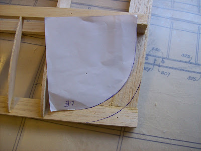
The wing tip leading edge curve was drawn onto the balsa using a simple
paper template then trimmed to size and sanded to the correct contour.


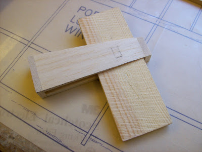
All the spar tip extension tapers were drawn onto the
wood then carefully cut out with a 'pull' saw

Here the leading edge curve has been cut and sanded.

A 'pull' saw is also visible along with the 'Perma-grit' sanding block. If you haven't got a 'Perma-grit' sanding block you can use rough abrasive paper glued to a wooden block and  that will do the same job.

I can't praise the 'Pull' saw enough it's a fantastic bit of kit, they're not cheap but they last for ever cutting through balsa wood and the cut is less that .5 mm thick and the blades are extremely sharp.


The underside tapers cut roughly to shape.
The upper tapers were cut in the same fashion.


These tapers were then sanded flat from the last wing
rib to the top surface of the wing tip


 To be continued...


Monday, 16 May 2011

Nieuport Build Part 3 - Top Wing Construction

PREPARATION

Before construction on the top wing could commence I needed to draw up the modifications for the revised aileron installation. Instead of the traditional setup for the ailerons, horn and push-rod connected to a servo in each  wing, I opted for the torque tube setup. This setup consists of torque tubes and bell-cranks in the wing with push-rods extending from the bell-cranks into the fuselage were they are connected to a servo.

The bell-crank and torque tube was the same method used on the full size Nieuports. It consisted of push-rods activated by the joystick that went up through the fuselage top decking to linkages on the aileron bell-cranks in the top wing that in turn were fixed to the aileron torque tubes that moved the ailerons.


 Centre section drawing showing some of the changes.


The above drawing shows the revised plywood wing fixing plates with cutouts to the centre that allows the rear top wing retaining bracket to seat correctly. Also visible are the two aileron bell-crank boxes, when the wings are covered these boxes remain open leaving the rear spar and bell-crank visible.


I then altered the drawing to allow for the torque tube installation. These tubes run from each plywood wing rib in the centre section through several balsa ribs and end about 75mm short of each aileron tip. The tubes end short to allow for the taper at the aileron tips.


The hinges are made from aluminium wire formed to fit tightly around the diameter of the torque tube, like a 'U' bolt fixing. The torque tube fits into a rebate cut in the aileron leading edge and the 'U' shaped wire fits around the rod and trough two holes drilled in the wing webbing of the aileron opening. A cut-out is also required in the aileron leading edge around the wire 'U' fixing to allow the aileron to move up and down freely. The tube has to rest on short spruce packers. These short packers, about 20mm long, act as bearings for the aileron torque tube to rest against and to form a gap around each aileron.


  Section through the aileron hinge fitting.


Hinge fitting and packing blocks.


Section through aileron tip showing termination point of torque tub.


The fist items I made for the top wings were the 2 bell-crank boxes, from 6mm sheet balsa stock. These boxes were made slightly higher than required so they could be sanded flush with the wing ribs at a later stage. The boxes would also require sanding to a taper and holes cut for the torque tube and spar before being glued into position.

 
 Aileron bell-crank boxes - I'll need these later, much later!!. Note the blocks
inside the boxes these were to ensure a parallel opening whilst the glue was setting.


Let the BUILD commence...

I wanted to build the 2 wing panels together so made the decision to 'Cut Up' the plan, I hate doing this but I knew it would speed up the build time. You can also compare the progress of each panel and keep an eye on the continuity.  I joined the plan at the wing centre section and pinned all 2375mm of it to the workbench!! It only just fit and I could see that making  the wingtips would prove a little tricky.

This is an old kit and doesn't have the luxury  of laser-cut components. All  the wing ribs were cut using a band-saw so it is important to pre-fit ALL  the ribs to the spars, leading and trailing edges, also check the fit of any plywood parts that may cut into any ribs.

After covering  the plan with a protective clear plastic film I placed the leading edges in position, pinning down first one end then the other, placing a straightedge between the two ends then pulling the wood up tight against the straightedge, this will ensure the wood is true and free from any curves.


Placing the components over the plan prior to assembly.


Port wing panel components, dry fit.


Starboard wing panel components, dry fit.


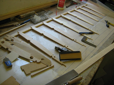
 Port wing under construction, ribs glued in place etc.


Centre section - note the port rear spar falling short of the
plywood wing rib. The aileron bell-crank box will be fixed here later.


To be continued...

Sunday, 15 May 2011

Nieuport Build Part 2 - Cockpit Detail

The cockpit detail was made from balsa wood, bass wood, hardwood dowel, stiff card, K&S aluminium tube, aluminium sheet, cotton thread, nuts & bolts, dress making pins, veneer pins, clear plastic sheet, wire, stain and paint to finish.


These are all the items made, control column, throttle lever,
instrument panel, seat and rudder bar assembly.


Control column - complete.


Closeup showing joystick pivot with linkages for elevator
cables and aluminium cross tube with aileron push-rod connections

Made from hardwood dowel (horizontal part shown unpainted) with a hand carved bass wood end attachment that was fixed to the dowel and holds the vertical joystick and the horizontal aileron tube. The joystick pivot is a section of aluminium tube with the ends flared out to retain it in the wooden housing. The elevator fixings are from aluminium tube, sheet aluminium, small brass nuts and bolts and brass veneer pins with heads filed flat to simulate fixings.


Elevator connection.


Aileron push-rod connection.

The horizontal aileron tube was made from aluminium and the ends were made from servo ball-joint fixings.The balls were filed flat on either side and the finished items were then glued into each end of the tubing. 


Joystick.

The joystick was made from hardwood dowel and the end detail was achieved by inserting the dowel into a rotating electric dill and using files to make the desired shape. The top of the joystick was then wrapped in cotton thread.


Throttle assembly - complete.


Closeup - top view


Closeup - side view.

The wooden support was made from balsa wood with a plywood facing to each side to hold the 2 levers in place. The levers were from piano wire, aluminium sheet, litho plate, wood for the handle and the head from a map pin. The frame was held apart with brass wire and aluminium spacer tubes and 2 nuts and bolts hold the finished unit to the wooden support. It was painted prior to final assembly.


Instrument panel - complete


Clock detail.


Altimeter detail.

The 2 instruments were made from paper tubes glued together with super glue and sanded to shape. Details are from aluminium tube, brass watch screws and small brass BA nuts and bolts. The dials were originated on a computer then printed out.  The hands were from paper soaked in super glue to give them rigidity and painted.


Oil level indicator detail

 This was made from a miniature test tube with a section cut off. The remainder was made from various pieces of tubing, wood, wire, nuts, bolts, washers and brass strip.


 Seat - front view, showing 2 aluminium fixing straps to seat base.

Seat - rear view showing the array of lightening holes.

Seat - Underside view, showing rear mounting brace, brace made from card.

The seat was almost entirely made from paper and card. A seat base was cut from card then the seat back was cut from stiff paper. The holes were marked in position and cut out, the edges were then soaked in super glue to add strength. The brace was made from thick card and the front fixings traps made from aluminium strip and fix to the seat with small nuts and bolts. The finished set was sealed and given a coat of paint then weathered to give that 'used look'.


 Rudder bar assembly - front view.


Rudder bar assembly - rear view


Rudder bar - closeup.

The main structure consisting of foot rests and framework were made from balsa wood and plywood.  The rudder bar support was hand carved from bass wood using an electric drill with cutting burr fitted and plywood for the base. Brass veneer pins with the heads filed flat were then added to the plywood base detail to simulate fixings. The rudder bar was made from balsa wood, balsa dowel and styrene sheet. A bolt was used in the centre to allow it to rotate and the same servo ball joints as used for the aileron push-rod connections were used to allow for rudder cable fixings.


Part 3 of the Nieuport Built - I will be constructing the top wing, complete with additions...