PREPARATION
Before construction on the top wing could commence I needed to draw up the modifications for the revised aileron installation. Instead of the traditional setup for the ailerons, horn and push-rod connected to a servo in each wing, I opted for the torque tube setup. This setup consists of torque tubes and bell-cranks in the wing with push-rods extending from the bell-cranks into the fuselage were they are connected to a servo.
The bell-crank and torque tube was the same method used on the full size Nieuports. It consisted of push-rods activated by the joystick that went up through the fuselage top decking to linkages on the aileron bell-cranks in the top wing that in turn were fixed to the aileron torque tubes that moved the ailerons.

Centre section drawing showing some of the changes.
The above drawing shows the revised plywood wing fixing plates with cutouts to the centre that allows the rear top wing retaining bracket to seat correctly. Also visible are the two aileron bell-crank boxes, when the wings are covered these boxes remain open leaving the rear spar and bell-crank visible.
I then altered the drawing to allow for the torque tube installation. These tubes run from each plywood wing rib in the centre section through several balsa ribs and end about 75mm short of each aileron tip. The tubes end short to allow for the taper at the aileron tips.
The hinges are made from aluminium wire formed to fit tightly around the diameter of the torque tube, like a 'U' bolt fixing. The torque tube fits into a rebate cut in the aileron leading edge and the 'U' shaped wire fits around the rod and trough two holes drilled in the wing webbing of the aileron opening. A cut-out is also required in the aileron leading edge around the wire 'U' fixing to allow the aileron to move up and down freely. The tube has to rest on short spruce packers. These short packers, about 20mm long, act as bearings for the aileron torque tube to rest against and to form a gap around each aileron.


 Centre section - note the port rear spar falling short of the
plywood wing rib. The aileron bell-crank box will be fixed here later.
I then altered the drawing to allow for the torque tube installation. These tubes run from each plywood wing rib in the centre section through several balsa ribs and end about 75mm short of each aileron tip. The tubes end short to allow for the taper at the aileron tips.
The hinges are made from aluminium wire formed to fit tightly around the diameter of the torque tube, like a 'U' bolt fixing. The torque tube fits into a rebate cut in the aileron leading edge and the 'U' shaped wire fits around the rod and trough two holes drilled in the wing webbing of the aileron opening. A cut-out is also required in the aileron leading edge around the wire 'U' fixing to allow the aileron to move up and down freely. The tube has to rest on short spruce packers. These short packers, about 20mm long, act as bearings for the aileron torque tube to rest against and to form a gap around each aileron.

Section through the aileron hinge fitting.

Hinge fitting and packing blocks.

Section through aileron tip showing termination point of torque tub.
The fist items I made for the top wings were the 2 bell-crank boxes, from 6mm sheet balsa stock. These boxes were made slightly higher than required so they could be sanded flush with the wing ribs at a later stage. The boxes would also require sanding to a taper and holes cut for the torque tube and spar before being glued into position.


Aileron bell-crank boxes - I'll need these later, much later!!. Note the blocks
inside the boxes these were to ensure a parallel opening whilst the glue was setting.
Let the BUILD commence...
I wanted to build the 2 wing panels together so made the decision to 'Cut Up' the plan, I hate doing this but I knew it would speed up the build time. You can also compare the progress of each panel and keep an eye on the continuity. I joined the plan at the wing centre section and pinned all 2375mm of it to the workbench!! It only just fit and I could see that making the wingtips would prove a little tricky.
This is an old kit and doesn't have the luxury of laser-cut components. All the wing ribs were cut using a band-saw so it is important to pre-fit ALL the ribs to the spars, leading and trailing edges, also check the fit of any plywood parts that may cut into any ribs.
After covering the plan with a protective clear plastic film I placed the leading edges in position, pinning down first one end then the other, placing a straightedge between the two ends then pulling the wood up tight against the straightedge, this will ensure the wood is true and free from any curves.

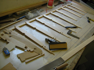
Placing the components over the plan prior to assembly.

Port wing panel components, dry fit.

Starboard wing panel components, dry fit.
 Port wing under construction, ribs glued in place etc.


plywood wing rib. The aileron bell-crank box will be fixed here later.
To be continued...
It is so good to have a blogger like you Mark.Now,we can all share your ideas and creations.
ReplyDeleteI will follow,closely,your Nieuport build.
My best wishes for your new blog.
Socrates
Hi Socrates,
ReplyDeleteWelcome to my blog and thank you for your positive and encouraging comments. I hope you enjoy the build as it progresses. I'll do my best to keep it up to date.
Best regards, Mark