The construction of the rudder, stabilizer and elevators are made mostly from 25 mm X 9mm stock balsa wood strip. After checking the contents of the kit box several times it became apparent that most of this wood was absent!! (NOTE: This wood was taken from the kit by me and used for something else many years ago. It was, however, originally supplied with the kit) Fortunately I had some balsa sheet stock of the right thickness so I cut some strips on the circular saw. I also cut all the gussets noting the direction of the grain. These gussets were all cut at 90 degrees and would be cut and sanded to the correct size on installation.
I started by cutting the balsa strip to approximate lengths and laid them in place over the plan. All the angles were then cut for the outline of each component, rudder, stabilizer and elevators.


Next, using a ballpoint pen I marked around the perimeter of the tailplane components that require sanding to a semicircular section, remembering to leave the elevator leading edges square. Also the entire rudder outline was sanded to a similar semicircular section.


Material cut to approximate lengths,
the curved parts were supplied with the kit.

Material cut to approximate lengths for stabilizer and elevators.

Stabilizer and elevator components glued together.
All the end grain wood was 'pre-glued'.
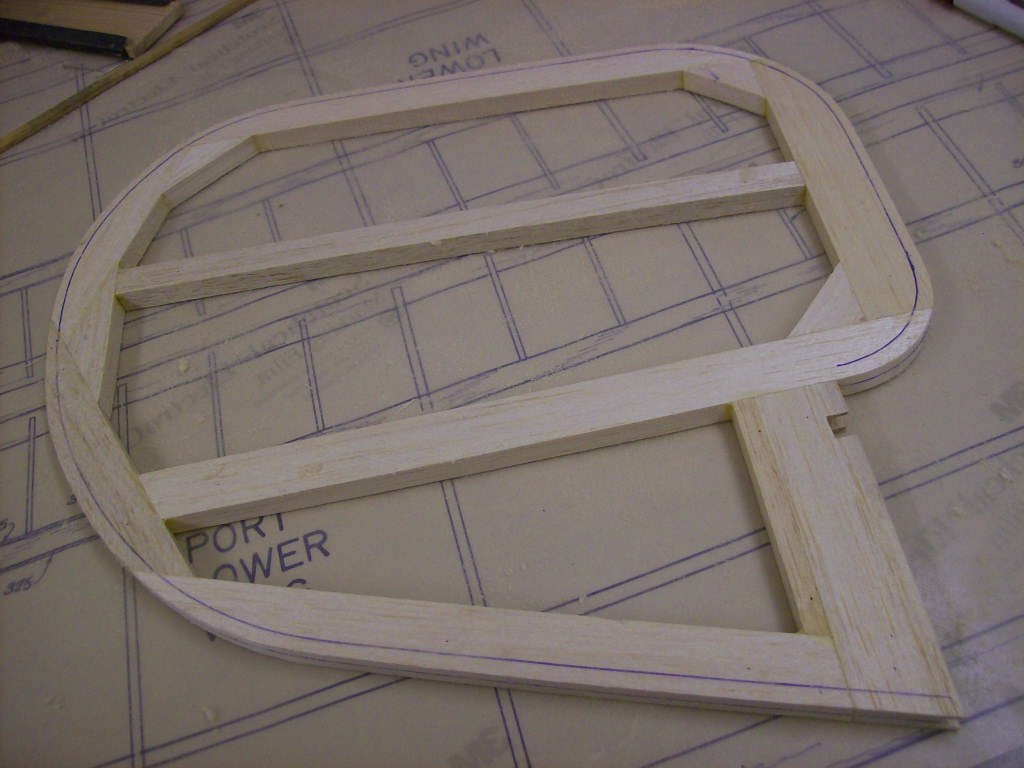
The above picture shows the elevator components assembled with all the gussets trimmed and glued in placed. The elevator leading edges have been rebated in the same way as the aileron rebates. But this time the rebate was narrower to accommodate a smaller diameter carbon fibre torque tube. The torque tube can also be seen as it was placed in the rebate to align the elevators during the build. After these parts were left to dry overnight the outline curves were drawn on then cut to shape and sanded at right angles ready for the next stage, planing and sanding the edges to a semicircular section around the outside shape. The trialing edge of the stabilizer and the rebated section of the elevators were left square.

Closeup of elevator torque tube, used to align the components.

Rudder shown assembled and glued together.
The lower hinged section of the rudder was
also rebated to allow for a torque tube to be fitted.
 Closeup of rudder rebate.
 Rudder removed from the plan and ready for sanding to finished profile.

In the above picture you can see the rebate in the vertical hinge post. Also visible is a circular hole in the horizontal balsa strip at the top end of the hinge post. The carbon fibre tube fits in the rebate and extends into this hole to help support the rudder when it is finally fitted to the sternpost.


Stabilizer and elevators removed from the plan
ready for sanding to finished profile.
A good way of sanding these components flat is to stick down a piece of abrasive paper with double sided sticky tape to a flat surface, block-board would suffice or better still as I do a sheet of 10 mm thick plate-glass. The part to be sanded is then rubbed over the abrasive paper in a circular motion until you are happy with the result. Don't get carried away though, it's easy to sand off the wood but a lot harder to put the wood dust back!!
Next, using a ballpoint pen I marked around the perimeter of the tailplane components that require sanding to a semicircular section, remembering to leave the elevator leading edges square. Also the entire rudder outline was sanded to a similar semicircular section.

Marking the edges ready for planing and sanding to profile.
The pen is held between thumb and index finger, and the middle finger and ring finger are pressed against the side of the wood then drawn from one end to the other. This enables a pen line to be drawn onto the surface parallel the edge of the wood, this technique has been used by carpenters for centuries. This line is drawn centrally to each edge that requires sanding. You then mark the top and bottom of the structure in the same way. The distance the line comes in from the edge is equal to half the thickness of the stock wood used during construction. So if the wood was 9 mm thick then the line drawn on the top and bottom surfaces would be approximately 4.5 mm from the edge.
Workshop Tip No. 3
When shaping a piece of wood, whenever possible, sand or plane down to a line. Lines are best applied with a ballpoint pen as they tend not to indent the surface like a pencil and can be easily removed with fine abrasive paper. Remember work to a line.
It is very easy to get carried away whilst happily listening to that therapeutic sound of wood-shavings parting company with your latest creation, but bear in mind the difficulty off putting those shavings back after planing away too much!!
Planing to a line alleviates this problem as it is easy to see how much wood has been taken off and how much is left to come off.


 Closeup of carbon fibre tube and hinge strap cut out.

Stabilizer and elevators marked up ready for shaping.
The stabilizer and elevators have been marked up ready for planing and sanding to shape. Also the hinge retaining strap apertures have been positioned and cut out. The carbon fibre tube will be cut to length later. The picture below shows the rudder marked up using the same process as above, the hinge strap aperture has also been cut out.
Rudder marked up and ready for shaping.
Next we plane down the edges to the straight grain areas and sand down those on the curves so as not to 'pull up' the grain whilst planing. After planing the shape was first roughed out using a coarse sanding block then made smooth using a fine sanding block.

Planing and sanding to section.

Planing and sanding to section.
Having the line to plane and sand to helps control the shape. If you plane or sand away the line then you know the shape is deviating. When the profiling was complete the pen line was carefully sanded off.

Pen line being sanded off.
With the components finished and sanded to shape I moved on to the hinge detail. I machined a piece of wood to the required section and cut it into short lengths.

Wood section used for the hinge bearing packers.

Hinge bearing packer section cut to length.
The stabilizer leading edge was then marked up ready to accept the 4 hinge bearing packers. These cut outs were aligned with the previously cut apertures for the hinge retaining straps. With the cut outs finished the hinge bearing packers were glued in position.

Hinge components less hinge strap.
The apertures were cut into the stabilizer and the hinge bearing packers glued in place. The hinge straps wrap around the carbon fibre tube and then each strap is nut & bolted to the hinge bearing packers.The carbon fibre tube rotates freely inside the hinge strap.

This picture shows the 4 hinge bearing packers
in position prior to gluing in place.
The hinge straps were then made from strips of aluminium, cut to length and formed around the carbon fibre tube. Holes were drilled in the hinge straps, top and bottom. The hinge strap was then placed over the wooden bearing packer and drilled through, half way from the top and half way from the bottom. Drilling the holes this way prevents the drill from wandering and missing the exit hole in the bottom hinge strap.

Closeup of hinge components.
The above picture shows a closeup of the stabilizer leading edge with the hinge bearing packer in place. The hinge strap fits around the carbon fibre tube then is nut & bolted to the hinge bearing packer allowing the tube to move freely. The elevator, seen in the bottom right of the picture above, will eventually be glued in place with epoxy to the carbon fibre tube. Note that the hinge strap cut out in the elevator has been reinforced with thin cyanoacrylate.

Closeup of hinge detail with elevator removed.

Closeup of hinge detail with elevator fitted.

Finished stabilizer and elevators with hinges fitted.

Rudder closeup with carbon fibre tube 'dry fitted'.
Rudder has also been sanded to shape in the same manner
as the stabilizer and elevators, cut out for hinge strap also shown.
Rudder has also been sanded to shape in the same manner
as the stabilizer and elevators, cut out for hinge strap also shown.

In the next post I will be sanding and shaping the top wings.
To be continued...
No comments:
Post a Comment