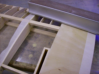
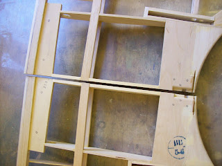
The top wing panels are almost ready for the .8mm plywood centre section sheeting to be applied, but first the aileron bell-cranks have to be pinned to the torque tubes with metal dowels.
The carbon fibre torque tubes had been marked up when they were cut to the correct length in the last post.
The first stage was to drill a 2mm diameter hole in the end of each carbon fibre tube so that the hole was on the centre line of the aileron box when the tube was fitted. This would allow the bell-cranks to sit centrally within the aileron box when finished.
2 dowels 15mm long were cut from piano wire and the ends were filed to a 45 degree angle to act as a 'lead'. This 'lead' makes locating each dowel through the holes in the torque tubes much easier.
Torque tubes, metal dowels and bell-cranks.
The metal dowels were placed through the holes in the torque tubes and then the bell-cranks slid onto the tubes until they sat up against the metal dowels.
Bell-crank, metal dowel and torque on wooden blocks.
Each torque tube, dowel and bell-crank was then packed up onto 2 wooden blocks to clear the end of the tube whilst the position of the dowel was marked onto the surface of the bell-crank with a scriber.
Both bell-cranks were marked up as shown above.
After the bell-cranks had been marked up they were cut out with a fret-saw and filed to size so as to obtain the correct fit.
Bell-crank with metal dowel fitted.
The main components, bell-crank with cut-out, dowel and tube.
The 2 finished bell-cranks and torque tubes with
metal dowels fitted. Not glued together at this stage.
Now that the bell-cranks are finished the 'scale' spar detail can be permanently glued in place. The 'scale spar passes through the rear openings in the centre section. The holes were opened up slightly so that the spars would be a good fit.
The 'scale' spar passed through the large
rectangular hole to the rear of the centre section.
The 'scale' spar, torque tube and
aileron bell-crank prior to installation.
Next the 'scale' spars were glued in place between the existing rear wing spars either side of the aileron boxes. At the same time the bell-cranks were also installed.
'Scale' spar in place with bell-crank fitted.
The torque tube is also visible but NOT glued in place at this stage.
The 2 'Scale' spars and bell-cranks fitted.
Again the torque tubes are visible but NOT glued in yet.
Now... the .8mm plywood centre section sheeting can be fitted...at last!! This sheeting has already been pre fitted and cut exact to size and the ends sanded to a taper. The plywood sheet was marked and taped into position before gluing the front of the sheet to the leading edge.
Centre section plywood sheeting marked up prior to gluing.
It was taped in place from this point back to the curved centre section cut-out
With the sheet held securely in position from the centre to the rear and unable to rotate, it is very important that the sheet does not twist, the front section was left free so that it could be pushed down onto the surface later. I then applied cyanoacrylate 'kicker' to the front edge of the plywood and medium cyanoacrylate to the leading edge.
The plywood was then pushed firmly down onto the surface of the ribs with a wooden block from the centre to the leading edge where it was held for a moment while the cyanoacrylate set with the aid of the 'kicker'.
The plywood centre section sheeting with the tape removed.
Now that the sheeting was held securely at the front the rest of the sheeting was glued in place with wood glue. Masking tape was used to hold the sheet down until the glue had set, over night.
Sheeting held in place with tape and 'G' clamps whilst the glue sets.
After the centre section had thoroughly set the 'G' clamps and tape were removed and everything was sanded down. The tapered ends of the plywood sheeting were then blended in with filler at the leading edge and centre section curved cut-out.
As the plywood centre section sheeting is applied to the top of the ribs and no allowance was made for the additional thickness of the ply you create a 'step'. This 'step' will be emphasized when the covering is applied so it's best to 'blend' it into the structure.
Plywood centre section sheeting applied and 'step' created.
It needs to look like this...
To achieve this it will be necessary to add some strips of balsa wood here and there. The 4 pieces of balsa that were glued to each spar, front and rear, were pre sanded to a taper.
There were 7 pieces of balsa cut for each wing panel.
The 7 pieces were than glued in place with medium cyanoacrylate for speed then sanded down.
Pieces glued in place prior to sanding.
Sanding the wood down.
To prevent some areas from being sanded down 'masking tape' was applied. And finally the excess 'scale' spar was sawn off and sanded flush with the centre section rib.
'Scale' spar installed and sanded flush.
The 2 centre sections finished.
The 2 centre sections finished.
The top wing is pretty well complete now. The aileron hinges require installing and the underside of the centre section of both top wing panels require a 'land' making around the front aluminium centre section strut mounting. This 'land' is required for the covering to adhere to and will be made when the lower wing panels are fitted to the fuselage. I intend to fit the top wings to an inverted fuselage, as the top wings are flat, then fit 'temporary' interplane struts whilst the lower wing panels are fitted. The wings will be rigged at later stage.
When the interplane struts are made and finished off they will replace the 'temporary' ones used earlier. Once the actual interplane struts are installed the wings can be rigged. However, final tensioning of the rigging wires will be done at a later stage, setting the incidence and washout etc.
Remember ALL the rigging wires are functional and should NOT be omitted.
To be continued...


