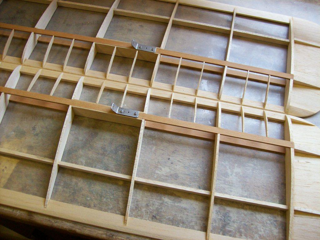
Now that the rigging brackets have been made it's time to fit some of them into the wing panels.
There are 2 brackets to each of the top wing panels and they fit to the underside. The lower wings have just 1 bracket to each panel and they each fit to the top of the panels.
Do you remember that saying, 'measure twice cut once'?
Well, now is a good time to 'measure twice and glue once'
Make sure the brackets are in the same position on each wing panel, a 'mirror image'. It's always worthwhile checking the plan as I was caught out once because the positions on the plan were incorrect! The aforementioned plan will remain anonymous but it was from a leading kit manufacturer. So it pays to check.
Some designers only draw one side of each wing panel and then reverse print it for the other side. This prevents 'human error' as each panel can only be identical.
Workshop Tip No. 7
There is a simple check that you can do to make sure a drawing of a wing (or other 'mirrored component') is the same on both sides. Fold the plan in half along the centre line of the wing then hold the drawing against a window, instant 'light box'. The daylight will shine through the drawings enabling you to see a superimposed image of the 2 wing panels. Aline the 2 wing panel drawings then move the top drawing slightly from left to right or up and down and you will soon see if there are any anomalies. If you do discover any discrepancies the amendments can be carried out at this stage instead of carrying them out after the construction has been undertaken.
There is a simple check that you can do to make sure a drawing of a wing (or other 'mirrored component') is the same on both sides. Fold the plan in half along the centre line of the wing then hold the drawing against a window, instant 'light box'. The daylight will shine through the drawings enabling you to see a superimposed image of the 2 wing panels. Aline the 2 wing panel drawings then move the top drawing slightly from left to right or up and down and you will soon see if there are any anomalies. If you do discover any discrepancies the amendments can be carried out at this stage instead of carrying them out after the construction has been undertaken.
I started with the lower wing rigging brackets. As there are only 3 holes to drill for each. All the brackets have holes in the centre to locate the interplane strut. The interplane struts have a metal rod glued into the ends, these rods then locate into each rigging bracket centre hole.
The bracket was clamped to the spar and a centre hole drilled through. I then inserted a bolt through the hole in the bracket and spar and held it in place with a washer and nut. This prevents the bracket moving whilst you are drilling the other holes in the spar, it also keeps everything aligned.
The two holes either side of the centre hole in the spar now require opening up to allow for the captive nuts to be pressed into place, I used a small 'G' clamp for this.

Bracket bolted on and captive nuts securely glued in place.
Once the captive nuts were secured with glue the other .8mm plywood spar webbing was glued in place making a strong 'box section'.

Close-up of lower rigging bracket and ply webbing to both sides of spar.
The lower wing panels showing rigging brackets in place.
Placing the wing panels together confirms the 'mirror image' of the rigging brackets and other components...now for the top wings.
The top wing rigging brackets can now be fitted. I cut the beech wood blocks to size and pre-fit them between the two wing ribs, 4 off in total.
When gluing these rigging blocks in place it's a good idea to bevel the corners slightly to the face being glued. This will ensure a tight fit against the leading edge for the front blocks and tight fit against the aileron webs for the rear blocks.
A fillet of glue will have been created when gluing the ribs to the leading edge and aileron web. If the corners of the blocks are left square these fillets of glue prevent the blocks seating correctly and can cause a gap that holds the blocks away from the surface, this will weaken the bond, and remember these blocks will be holding the wings on!!
The holes for the top wing blocks were marked, centre-punched and drilled using the same procedure as that used for the lower wings. The only deviation being the use a small drill press to keep the holes at 90 degrees to the surface of the blocks. The holes in the lower wing spars were drilled freehand as the wood was only 4mm thick.

Top wing rigging blocks marked up ready for drilling.
The beveled corners can also be seen.
The beveled corners can also be seen.

Top rigging block being drilled with a drill press.
I have also 'centre punched' the mark to locate the drill point whilst drilling.
Once the holes had been opened up the captive nuts were fitted, again with the use of a small 'G' clamp to press them into position, in the same way as that used for the lower wings, and not forgetting to glue them in place with epoxy. There is nothing more annoying than pushing a captive nut out whilst trying to thread a bolt into it!!

Top wing rigging blocks with brackets attached.
After everything had been 'dry-fit' all four blocks were glued in position and held in place with masking tape until the glue had set.

Blocks held in position with masking tape whilst the glue was setting.

Glue set and masking tape removed.

The brackets were then removed, identified with a number and put aside ready for use later.

Metal rigging brackets removed.

The top wing panels side by side, a visual check
that everything is in the same place, a 'mirror image'
In the next post I'll be fitting the top wings to the fuselage and marking the holes for the captive nuts.
To be continued...
No comments:
Post a Comment